Victoria Thunder Tiger Description
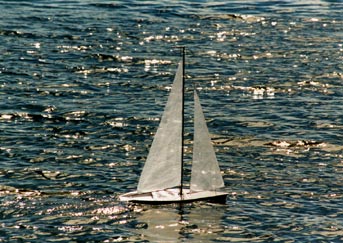
This is a radio controlled sail boat. Advances in miniaturization of radio control equipment, high technology construction materials for the hull and rigging, and small batteries have resulted in models that work like the real thing.
The boat is really fun to sail, responding quickly to the controls and moving quickly even in small winds. It is easy to build and later modify to improve performance. Care must be taken when modifying your boat as many modifications are not allowed by the class rules and will make your boat ineligable for competition.
I gave my father-in-law a kit, so I would have someone to race. He built a standard Victoria by Thunder Tiger. I was not happy with the standard version and so decided to modify my boat.
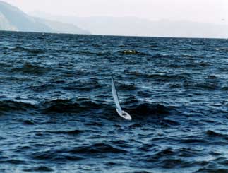
Modifications:
The objectives for many of my modifications were simple.
- water tight: No boat will ever be completely dry. I wanted to make mine as dry as possible.
- ease of rigging: The cleats and line adjusters were difficult for me to use. I wanted to be able to make adjustements easily and for the adjustments to be retained, no matter the stress or wind speed.
- increased strength: Some of the components are weak and subject to breaking or cracking. These needed to be reinforced or replaced with stronger material.
- weight reduction: Reducing the weight in general, and above the water level in particular will make the boat respond more quickly, both in turning and acceleration.
Do not modify your boat if you expect to compete in the Victoria Class. Only certain modifications are allowed and must be carefully considered before doing them. Many of the modifications below will help solve multiple problems but most are not legal for competition.
The hull is vacume formed and has some thin areas. Additional fiber glass reinforcements were added in the bow to prevent water leaking. The keel area is also weak, so some plywood and glass were added here as well.
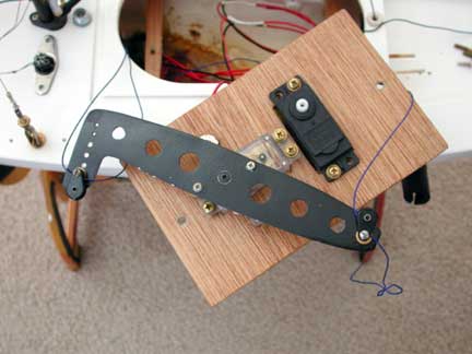
Two stringers were added across the hull on which to mount the servo and receiver board. Note the two holes at each end of the board and the holes in the stringers. The stringers have nuts epoxied to the bottom of the stringer and the receiver board bolts through. The four batteries, now NiMH rechargables, are installed in two battery holders and mounted with double stick tape. The batteries can be moved around in the bottom hull to balance the boat. I will use Velcro fastening tape next time.
The sail servo has a new arm fabricated out of thin aluminium. The pulley on the left of the arm adjusts the main sail and the one on the right adjustes the jib. The receiver is mounted under the board in the continued effort to lower the weight in the boat.
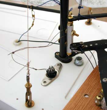
The keel is attached with a Nyloc nut, in order to prevent loss while at sea. The stays are attached to brass eyes, bolted into small wood ply plates under the deck. The stays are attached to clips similar to those found on model aircraft linkages and are removable. Small loops have been soldered to allow attachement of the lines. These allow tensioning of the rig.
The mast is a carbon fiber tube, found at many kite stores. Many of the rigging materials, including sail cloth can be found online at kite supply houses. The boom and jib boom are also carbon fiber and have small brass cotter pins inserted in small holes where lines need to be attached. I used fishing gear for many of the line connectors and fishing line for most of the lines.
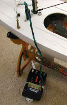
The on and off switch is actually also the battery charging port. A five pin DIN connector is mounted to the deck. It allows wiring access to each separate battery pack and to the receiver and servos. The plug shown in the picture above, is connected to a string attached to the mast base, and is for sailing. When plugged in, it connects the batteries to the receiver and servos. When the plug is removed, the boat is effectively turned off.
Another plug shown to the left, is connected to a battery charger and can be inserted in the socket. Now the batteries are connected to the charger and the batteries can be charged without removing them.
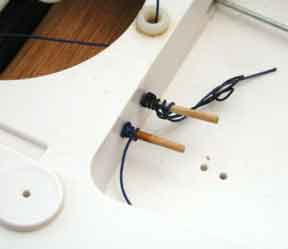
One of my biggest complaints was the difficulty of using the small cleats and line adjusters.
In order to adjust the jib and main sail lines, I lead the lines through the holes into the cockpit. I then plugged the holes, effectively pinching the lines in place, with tooth picks. The remaining line was looped around the picks with half hitches. Not elegant but it worked.
The through deck fair lead is a Nylon concrete fastener with rounded edges. This eases the movement of the line through the deck and provides some mimimal water protection with a raised area.
The hatch cover is clear plastic sheet, as found at the local office supply and is attached using 3M tape. The type of tape used to water proof model power boats has been extensively tested and works well.
The masthead crane was fabricated out of aluminium and has two brass bolts and nuts to allow adjusting jib tension and main sail height. The line is wound around the bolt once and the nuts tightened. Again, not elegant, but easy to do.
Many lines were upgraded to a 60 pound test line. The line has a flattened oval cross section and when tightened, vibrates in heavy winds. It is an amazing sound, similar to that found on real boats as the wind hums and screams.
Information Sources:
These were sources for information when I built my boat. However the links are unreliable so you might try a search by the various names below.
Victoria Resource Center: articles, rules, registration, construction suggestions
Victoria One Design: American Model Yachting Association, register your boat for racing, rules
Hang-em-High: on line kite supplies
See rec.models.rc.water news group, which covers mostly radio control power boats but does have some contributors that know sail boats. Avoid people that constantly correct your terminology. They show little patience for those of us learning a new hobby and prefer to correct rather than teach.
