Sous Vide Temperature Controller
Introduction
I discovered a long, extremely well written article on the Seattle Food Geek website, written by Scott Heimendinger. It shows how to build what he calls a Sous Vide Heating Immersion Circulator for about $75. I was excited! His article was detailed and showed how to build a self contained sous vide cooker, including heating elements, circulation pump, temperature controller and probe. It mounts on the side of the cooking container.
I decided to build one but with some modifications. I decided I wanted the following features:
- I wanted the controller to be separate from the heating method. My controller has a regular duplex socket in the back so that any heat source can be controlled. I plug a small hot plate into the back. The controller can also be used with fondue sets, slow cookers, and rice steamers.
- The temperature probe plugs into the controller. The probe can then be positioned in the liquid and can be easily replaced.
- I used a 20 ampere solid state relay. The relay is capable of driving most hot plates and other heating sources.
- The water needs to be circulated in order to prevent hot spots. An aquarium submersible pump is place in the bottom of the pot and can be easily replaced. See problems with this approach below.
IMPORTANT NOTICE
This is an electronics device. You should build the sous vide controller only if you are comfortable working with electricity. The process below worked for me but I make no claims it will work for you. As always, exercise care when building electronic devices.
Acquiring the Parts
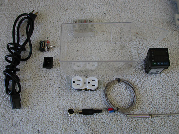
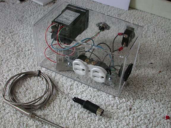
Included in the picture above are the line cord, switch, and socket for the end of the line cord on the left. The duplex socket, DIN socket and plug, wire and probe for the thermocouple are sitting in front of the case. The SSR, solid state relay is behind and the temperature controller is on the right. Note the holes have already been cut in the case but are barely visible because the case is clear.
I first went to Amazon to look for the temperature controller. I chuckled because the page included what other things people bought when purchasing the controller. All the items were from Scott's article, including the plastic container, temperature probe, and immersion heaters! There was plenty of confusion about which temperature controller to buy. Here is a list of the items I bought:
- storage container by Acrylic - 4 inches x 4 inches x 7 inches
- Sunterra fountain pump, model 104506, 30 gallons per hour, sold by Amazon
- heavy duty toggle switch (best purchased at the local hardware store
- duplex wall socket (best purchased at the local hardware store
- temperature controller, model JLD-612, with SSR output, sold by LightObject.com
- PT100 PID precise 0.1 degree thermocouple, sold by LightObject.com
- 25A Solid State Relay (SSR), sold by LightObject.com
- mini-DIN panel mount socket and cable mount plug
- line plug and panel mount socket, purchased at the local electronics supply. You could use a cheap extension cord instead.
The storage container is a good size for several reasons. It holds all the components and is large enough to fit my hands inside to make the connections. My box is oriented differently in order to make room for the electrical outlet on the back.
The Sunterra pump was recommended because it was quiet. It was very quiet when first installed but is now noisy. It may not survive the high temperature. More on this later.
I considered installing a ground fault interrupter instead of the duplex socket. The GFI will sense if a person is getting a shock and will turn off quickly. I decided to install a plain duplex socket for a couple of reasons. First our kitchen outlets are already protected by a GFI and second, many of the appliances I plan on pugging into the temperature controller have only two prongs and are double insulated, reducing the probability of getting a shock.
There were several other temperature controllers available making it difficult to decide which one was correct. Making the decision even more difficult, there were identical controllers under different brand names. As Scott emphasizes, get one with an SSR output and get an SSR relay. I restore pinball machines, see index to the right, and am very familiar with relays. I could have wired a relay in place of the SSR and used the relay outputs of the temperature controller. Watching the controller in action, with frequent on/off cycles, the SSR relay is a much better solution.
I wanted a way to disconnect the temperature probe from the controller. This helps with storage and mounting a new probe if I break the old one. There are many choices for plugs and sockets. The mini DIN seemed like the best choice. You could use any plug and socket with at least three conductors. The mini DIN was used extensively for head phone and microphone jacks on computers and is readily available. I have included a couple of pages from the Mouser catalog to show these parts. (Note these pages are from around February 2011 and will certainly have changed by now. (Sockets and Plugs ) My second choice was to use a stereo headphone jack and socket as these have three conductors as well.
Cutting the Plastic
Cutting the box was fun. I traced the items that needed to be mounted onto the plastic. I then did a rough cut with my Dremel rotary tool and a router bit. This melts the plastic as well as cuts it and so I stayed far enough away from my lines so as not to deform the clear plastic. Later I returned to make a fine cut along the line, at a much slower pace, thus avoiding over heating.
Some of the components mount from the inside and some use a panel mount. The panel mount pushes into the hole from the outside and then springs hold it to the container. The temperature controller, line cord plug, and DIN socket all mount this way. The on/off toggle switch and the duplex socket mount from the inside. The duplex socket and the DIN socket both need small screws to hold them in place.
Mocking Up the Wiring
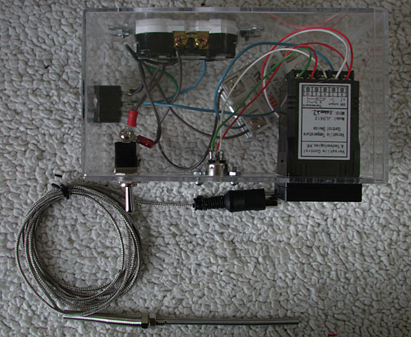
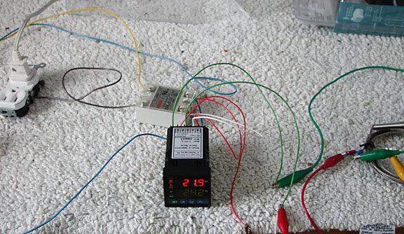
Above, you can see the temperature controller is showing the current ambient of 21.9C. The temperature controller turns the solid state relay on and off, in an attempt to make the temperature of the probe match my desire input temperature. The solit state relay, SSR, is behind the controller. It in turn is turning the socket on and off. A lamp is plugged into the socket and is turning on and off in response to the solid state relay. To the right is the thermocouple, with red, green, and yellow clips holding the controller wires onto the thermocouple wires.
I wired the controller together before installing any of the components in the box. Once you have it assembled, it is not impossible but definitely difficult to change the wiring. Here is a wiring diagram along with notes about my particular application. Please take care when connecting to the PID controller and the solid state relay. The output from the PID is direct current so the output of my PID needed to be connected to the correct + and - terminals of the solid state relay.
When performing the "smoke test", I found the display showing EEEEE, an error usually associated with the input. I followed the instructions to make sure the controller was expecting the correct PT100 thermocouple. Apparently there are several variations on the color coding of the three wires coming out of the thermocouple. I assumed the + on the controller expected the red wire on the thermocouple but I was incorrect. Playing with the three wires, in almost all possible combinations, resulted in a correctly working device. I was happily putting the thermocouple in my iced water and then holding it in my hand to warm it. I chuckled because I have my work bench light plugged into the output socket and it was going on and off in a vague attempt to heat up the thermocouple.
Assembly
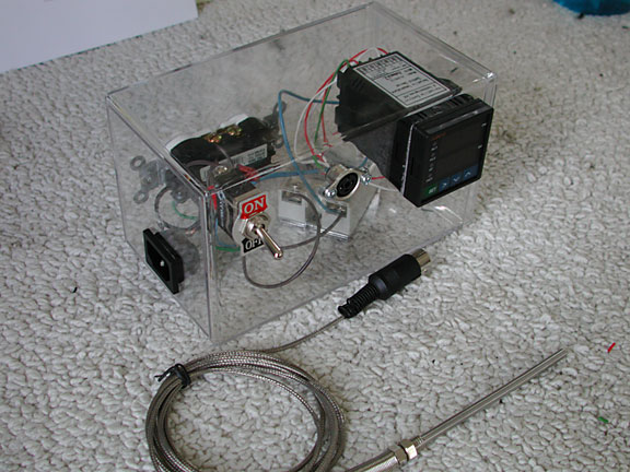
The picture at the top of the page shows the sous vide temperature controller as a complete assembly. The picture above shows the back of the controller with the socket. The pot, steamer or other device is plugged in here. Later I plan on plugging in a hot plate with some smoking wood on it and I will place the temperature probe in the smoker. The controller will maintain the temperature in this application as well.
Mounting all the components to the acrylic box was easy. I cut most of the wires to shorten them but there was still enough slack so I can remove something to gain access. The duplex socket and DIN socket were screwed to the plastic and the wiring added to the switch. I soldered wires to the mini Din socket and plug and to the line plug.
Water Pump
One of my concerns was the durability of the water pump when it is immersed for hours in hot water. Most of the pumps specify a water temperature much cooler than my application. The cost is not high so I just went ahead and used the Sunterra. Sure enough, after a couple of months usage, the pump started having difficulty getting started. Finally I decided to take it apart and see what the problem was.
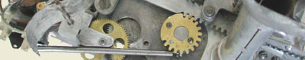
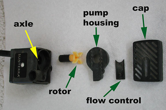
Great news! The pump basically snaps together. So it is easy to disassemble. The cap comes off first. Then the pump housing slides off the main housing. The flow control slides into the raised groove on the housing and so it is easy to slide it off. Finally the rotor can be lifted off the axle. There are no bearings to go bad! This pumps is perfect for this application. (There might be long term issues with the winding inside the housing but I doubt it. It is potted and should be waterproof.)
Clean the pump housing and cap with a tooth brush. The rotor can be wiped clean, especially the black magnet area. Finally the inside of the housing around the axle can be cleaned with a Q-tip. I put a drop of oil on the axle before assembling the rotor, however this will disappear quickly when the rotor is running in hot water again. The flow control gate can be slide into the housing and the housing replaced. Finally the cap can be snapped back into position.
My grand-daughter, Adia, did a science experiment with the sous vide controller. She measured the temperature at which the egg yolk and white solidified. She started with temperature extremes and did a binary search to find the correct temperatures. As a result of the very high starting temperatures, the water pump melted and stopped working. A substitute water circulation method was used, an aquarium air pump. This caused bubbles to rise up from the bottom, thus moving the water around. Unfortunately it also increased the surface area greatly, causing more water to evaporate from the pot. Care must be taken to maintain the water level.
I am thinking of other ways to circulate the water. Perhaps a stirring method might work better, but then you have to make sure the plastic envelopes do not get caught in the blades.
I am currently using an ECO Plus 66 submersible pump but it suffers from the same weaknesses as the Sunterra pump.