How to Illuminate your Spilhaus Space Clock
By Ben Langlotz, Patent Attorney
There is an inexpensive, practical, and attractive way to illuminate a Spilhaus Space Clock, and it’s easy to imagine that Professor Spilhaus would have employed the method if it had been available. In contrast to the dim orange illumination provided by the original incandescent bulbs that are now hard to find, it’s a nice upgrade to fully illuminate a Space Clock to make it much more readable and visually striking. The project does not remove or replace the existing illumination, so purists will be able to enjoy the clock unilluminated or traditionally illuminated without any apparent difference. No modification of the clock is needed, but some minor modifications may be desirable.
This project requires removal of the works, and a scrupulous cleaning of discs and windows is advised to avoid revealing dirt and dust. We used less than 5 feet of LED tape light. The depicted example uses Kichler 4T series 12V tape light that is 10mm wide (the link is to a 16-foot example that is triple what is needed). The example tape has an output of 1.5 watts per foot. This has an adhesive backing that is the only thing needed to adhere to all of the interior clock case surfaces (after wiping and dusting). 2700K provides a warm color temperature that is well-suited to interior environments. 24V and high-brightness options are not advised as this is brighter than most will prefer without dimming. Kichler is a premium brand and the illustrated project used leftover scraps from a shelf lighting project where it is now displayed and depicted. There are many other options at lower cost, and in the author’s opinion 1W/ft would be ample, and 0.5W/ft probably adequate. The author used white-surfaced LED tape, and this is not noticeable or objectionable, but black may be preferred if available.
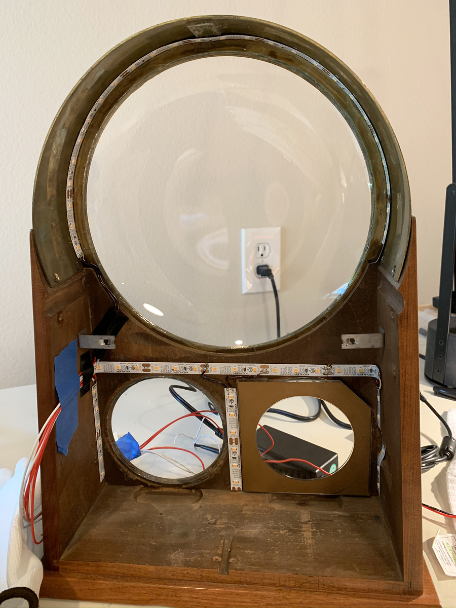
The layout of the tape strips inside the housing includes a longer strip at the forward edge of the interior of the arch, centered in the housing. A gap between LED lamps is centered at the top astride the upper disc support block. Because LED tape has definite length of segments it may be cut to (the Kichler is 2.5”) this segment needs to be planned to be even at each lower end, without centering an LED lamp at the top where it may be obscured and break up the even “sparkle” pattern of LEDs visible in reflection. Tape with a different segment length may enable a slightly lower coverage. In the author’s clock, there was some hardened sealant at the seam between the forward edge of the brass arch and the front panel, and this variable lumpy residue was removed to be able to evenly position the main tape smoothly against the arch interior, and flush against the front panel. Positioning the LED tape rearward to avoid this adhesive caused the side glare to be more visible.
The short vertical lower side strips are on the side walls, with the right (as seen from the back) clock side strip bent to follow the contour of the case cutout. In this example, the case was carefully chiseled to form gentler ramps and ensure clearance and adhesion, but this is probably not needed.
The horizontal strip positioned above the sub-dials is on the front panel, and this is as low as possible to reduce unwanted reflections off the main discs. It was slightly longer than the space, and is bent at the ends. This enabled the inclusion of another segment, but is probably not needed as light in the corners away from the openings is least critical. The short vertical center strip illuminates both sub-dials, and no illumination from below is possible or seems to be needed in the end.
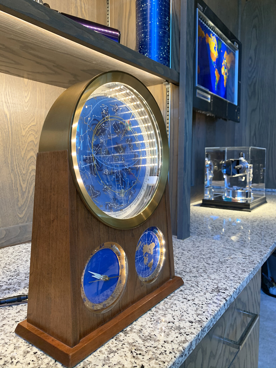
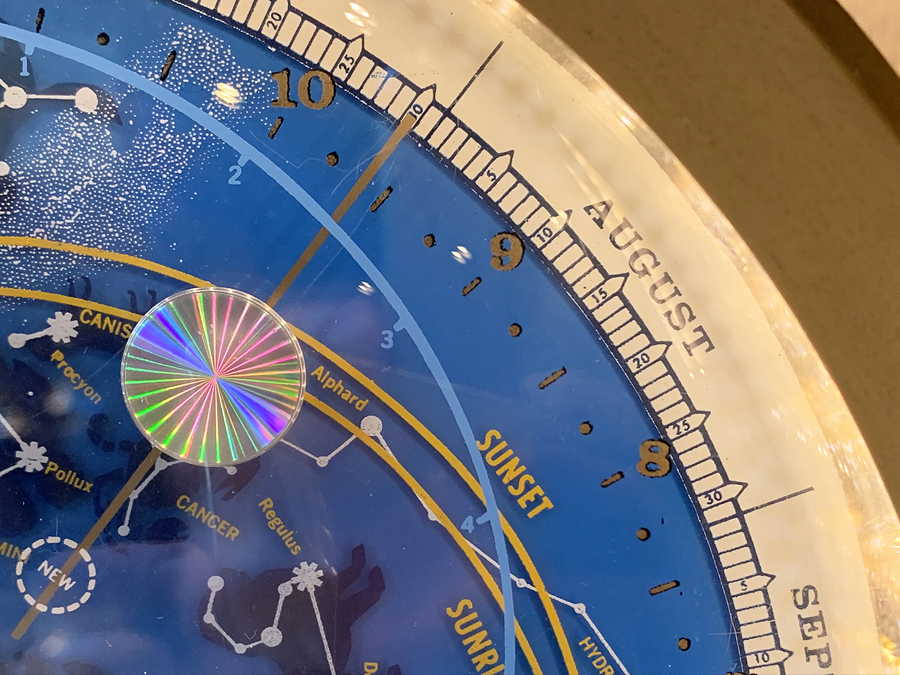
There is some unobjectionable visibility of the LEDs from extreme angles, and experimentation led to the depicted configuration as the best illumination without undue glare. The ability to dim to a pleasing level and positioning the clock for viewing has a helpful impact on any unwanted glare. In general, the most notable glare is from the reflection of the strip of LEDs over the top arch, and this is a pleasing “stellar” effect that is in keeping with the aesthetics of the design with its visible gear teeth. These LEDs also generate a pleasing rainbow star effect on the reflection grating sun and moon symbols.
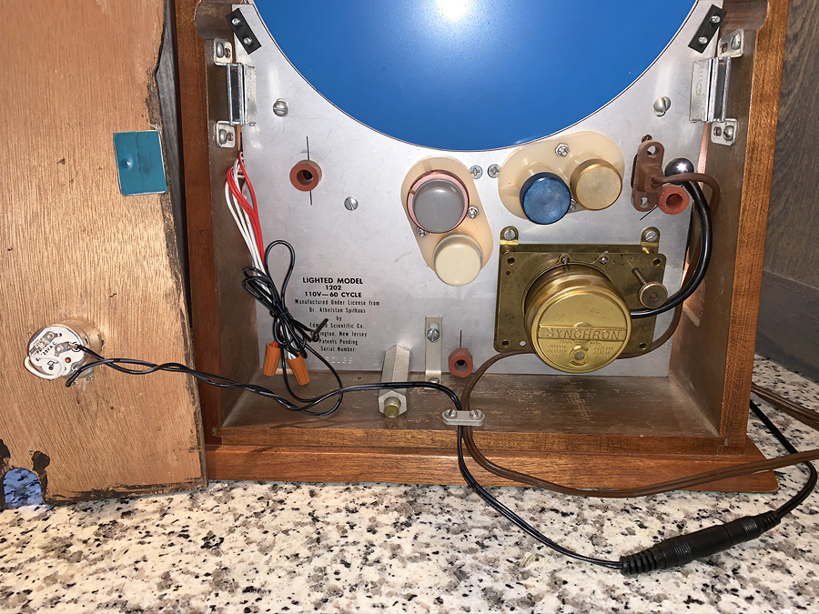
All the strips are interconnected (before adhesion) using simple solder connections, and the low wattage (not much more than about 2W for the largest strip) means that light wire gauge of 18 ga (maybe less) may be used. To avoid a nest of wires that may interfere with operation or be visible to viewers, this example used short wires to jump to nearby strips, with all the leads coming off of one side to extend to the rear of the works main frame panel. For example, the middle vertical lower strip is jumpered to pads at the middle of the horizontal strip, which also has a connection to the right strip on the side away from where the low voltage wire bundle bypassed the main clock frame plate. Black wire insulation is suggested to avoid any red or white wires in the brightly lit space being noticed by observers. LED tape makers offer push-in end connectors for those who are uncomfortable with soldering, but these add cost, bulk, and require management of cable runs within the clock.
There were several modifications to the clock that may not be necessary. As mentioned, the recess in the sidewall for the large hour gear was chiseled to create a slope at each end for that strip to adhere to. The top disc support block was trimmed at its top edge to ensure that it fit between the top two LED lamps to ensure it didn’t block the light, but with restraint to avoid weakening it.
After tape installation, the works may be reinstalled. Taping the low voltage wires in a flat ribbon the to the side panels facilitates them bypassing the works plate. These need to be connected to each other with wire nuts or other means, and to a power supply.
Any low voltage 12V power supply with at least 5W capacity is suitable (this converts to 0.4A or 400mA). 12V 6W (500mA) “wall wart” chargers are very common, and a higher wattage charger is fine. In fact, 9V generates pleasing results that are only slightly dimmer, and a 9V battery is a handy temporary power supply for testing during assembly. A set of Minigrabber test leads is extremely helpful for temporary connections during assembly and test. The depicted example is driven from an existing hard-wired and wall-dimmed 12V transformer that drives the shelf lights. This way, when the lights go off at the end of the day, the clock lights do to even ass the clock continues to keep time. A female 5.5X2.1MM jack (common on many chargers for laptop computers) dangles out the rear of the clock along with the power cord, and connects to the male on a power cord coming from the existing power supply. This was made from a “CABLE ASSY 5.5X2.1MM” from digikey.com, a good source of electrical supplies, with a website than can be daunting – call their customer service to help you make the right selection.
Most upgraders will want to have a plug-in wall converter that supplies the new lights, even though this means two plugs. It’s possible to wire a transformer to the AC inside the clock case for one plug, but this means that the lights will be on all the time and not externally dimmed, unless a switch is added, or the lights are wired into the existing AC switch after safely disconnecting that switch from the AC power (electrician level capabilities required). The depicted clock retains the original lights, which can be turned on in addition to or instead of the LEDs. It’s also possible to imagine plugging in the clock and the light transformer into the end of an extension cord inside the case or strapped to the back to provide a single plug, but there may not be space for these cumbersome options.
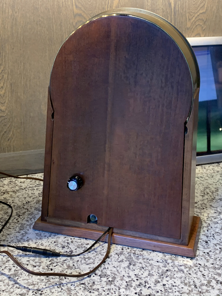
The depicted clock has a rotary dimmer that was mounted to a hole drilled in the back panel. The dimmer is simply a 0-100 ohm rotary potentiometer that is wired in series on the 12V line. The 5W capacity is based on the 5W consumption of the LEDs. When set to max resistance, this doesn’t dim all the way, but to about 20% of max brightness. Others may wish to experiment with higher resistance, and one sensible approach is to select a lower voltage transformer – 9V is suitable, while 6V was found to be inadequate to drive the LEDs. The dimmer has a switch to provide a click off option. The depicted example is located 3” up from the bottom edge of the panel, and 2” in from the left edge to provide clearance from clock knobs. A suitable knob can be attached. Because it is hard wired to the LEDs, the panel is not fully separable from the clock without removing the switch. If that is desired another two-line jack is needed – just buy another male-female cord and use the ends. Those who don’t wish to drill the back panel may use a housing for the dimmer and leave it outside the box.
The primary skill needed for this upgrade is proficiency with a soldering iron. The greater challenges involve simply removing the works and arranging presumably needed gear replacement. The project cost is minimal beyond the LED strips. The author’s only modification would be to try a higher wattage resistor potentiometer until it dimmed to dark, and to consider lower brightness LED strips.
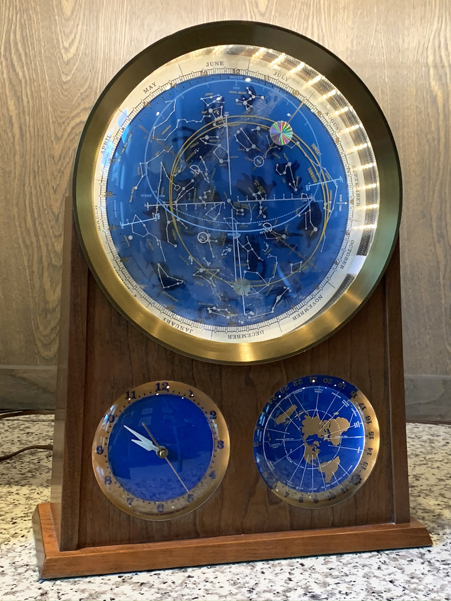
Original Light Appearance
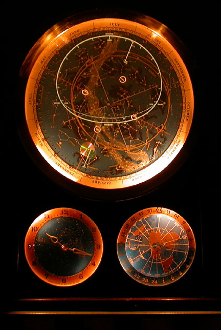
Original lighting appearance.