Adjust Lamp Duration:
According to the manual:
Shot Timing Potentiometer
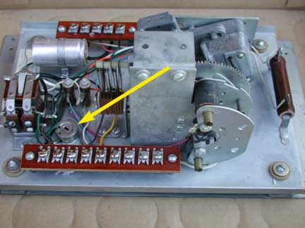
There is a shot timing potentiometer mounted on the Credit & Relay Assembly chassis in the gun stand. This potentiometer, designated as R31 on the schematic diagram, is connected across the coil of the shot timing relay. It is adjusted at the factory to give a gun lamp light pulse . 10 - . 13 seconds long. Turning the potentiometer arm clockwise lengthens the light pulse duration - a maximum length of approximately . 20 seconds can be obtained.
The adjustment of the potentiometer should not be done unless there is a specific reason to believe the current setting is not providing the desired effect. Adjust the sensitivity if you want to make the game easier. To adjust the Shot Timing, it is best to do so with an oscilloscope, so that the duration of the relay being closed can be timed.
Philosophically, lengthening the duration of the relay is equivalent to turning the gun into a machine gun. The lamp stays bright for some length of time, and the player can track the target. If the light beam crosses the lens, a hit is detected, even when sweeping across the target. With a short duration beam, it is more like a single bullet. The patents are recommended reading if you want to learn the efforts the designers went to in order to similate a single bullet.

This is a Credit and Relay Assembly for a Coon Hunt and is complete. The arrow points to the Shot Timing Potentiometer, which is an enclosed pot with a slot for adjustment. Adjust it one way and the shot will get longer. Adjust it the other way and it will grow shorter. The relay itself is right next to the potentiometer. Unfortunately, there is no consistent direction to turn the adjustment to get longer or shorter. You will need to experiment. You can look carefully at the wiring diagram and turn the adjustment to reduce the resistance.
Reducing the resistance will allow more current to bypass the relay, reducing the amount going through the coil and causing the relay to close for a shorter time.

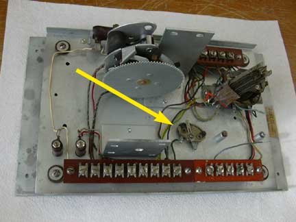
The older Credit and Relay Assembly had the potentiometer in a different area, closer to the gun terminals. This potentiometer is open, with the resistance wire visible and the wiper being movable for adjustment. The wire connected to the potentiometer is to ground and the relay will connect to the movable wiper. In this case, moving the wiper to the left, closer to ground, will reduce the resistance, and make the lamp duration shorter. Moving the wiper to the right will increase the resistance and move more current through the relay, removed for the picture, and thus reduce the duration of the flash.
Many Credit and Relay Assemblies have the potentiometer closer to the relay but on the same side as above, approximately where the post next to this potentiometer is.
