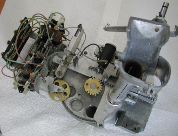
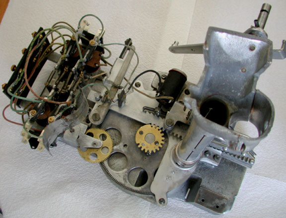
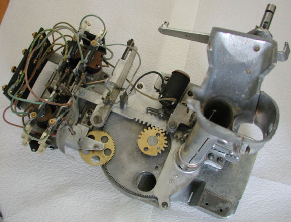


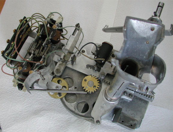
Jennings Sportsman (pinball) Payout Mechanism
(mouse over the buttons to see the steps or "PLAY" to see the animation)
With no winning combination, the player pulls the lever anyway, hoping for a free payout. The rack has not moved, but a slight motion causes the Payout Circuit Breaker to make contact.
The master switch turns on electricity but there is no payout combination. As a result, the small electromagnet does not raise a lever and does not power the large electromagnet. The ratchet on the rack prevents further movement of the rack and no coins are paid.
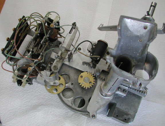
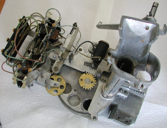
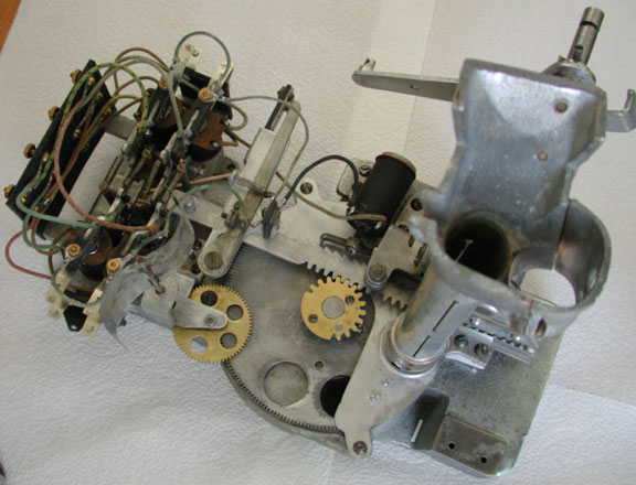
The player again pulls the lever, this time because he has a winning combination. (The return spring has been removed to allow the mechanism to be posed in various positions.)
With only a slight movement of the rack, the pin on the end of the rack allows the payout circuit breaker to make contact. This turns the game on, and allows electricity to flow to the playfield. The playfield switches allow current to flow, indicating a payout combination. There is also a payout latch on the bottom of the playfield that indicates a winning combination.
There is a winning combination and the small electromagnetic activates, raising the payout stop lever into the correct position. This also activates the large electromagnet, allowing the rack to move forward.
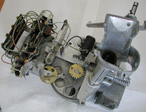
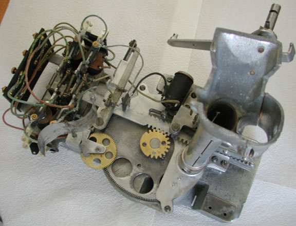
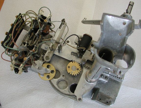
The rack continues to move toward the payout stop lever raisled by the small electromagnet, in this case preparing to payout six coins.
The rack continues to rotate the payout disc, picking up another set of three coins. The coins are rotated counter-clockwise, out of view.
The rack continues to rotate the payout disc, picking up another set of three coins. The coins are rotated counter-clockwise, out of view.
The rack continues to move toward the payout stop lever. The payout stop lever being raised, will prevent the rack from moving past that point and will limit the payout to the correct amount.
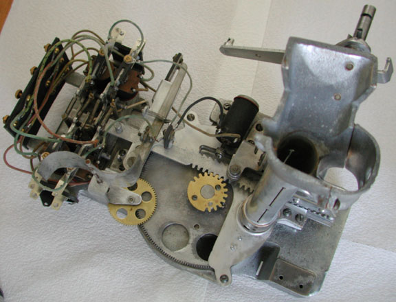
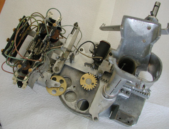
The tip of the rack finally reaches the payout stop lever. It first makes electrical contact which resets the payout latch on the bottom of the playfield. This stops electricity to the small electromagnetic, which in turn resets the large electromagnetic.
The rack is now withdrawn. The large electromagnet is no longer powered, and a ratchet hidden behind the payout tube now allows the rack only to be withdrawn and not pushed further.
As the rack is withdrawn, the payout disc continues to rotate, dropping batches of three coins into the payout hopper under the game.
The rack continues to be withdrawn and each batch of coins is paid
The rack is almost completely withdrawn and all coins are now paid.
The rack is now back at the start position and in the last bit of motion, it breaks the payout circuit breaker, stopping futher drain on the battery. The mechanism is now ready for the next winning payout.
Additional Information
See also the introduction, objectives and part naming diagram