Evans Races Relay Board Restoration
The Relay Board has much of the relay logic for the game. While there are a couple of relays on the mechanism board, most are on a slide out board that provides easy access for repair. The board slides out the front of the game, allowing the payout coin tubes to stand up higher and catch played coins.
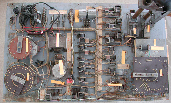
This is the board unrestored. The orange labels indicate various assemblies. This board has been modified to enable the operator to switch from payout to free play and back with just the flip of a switch. Normally the conversion requires a plug to be moved. Some creative technician added a score motor and switch to make the same connections that the plug would make. To make room for the score motor, the pinball randomizer was moved over by the payout tubes. These changes will be removed and the original layout will be retained. Later the ability to switch from payout to free play will be added but with the score motor hidden in the bottom of the game.
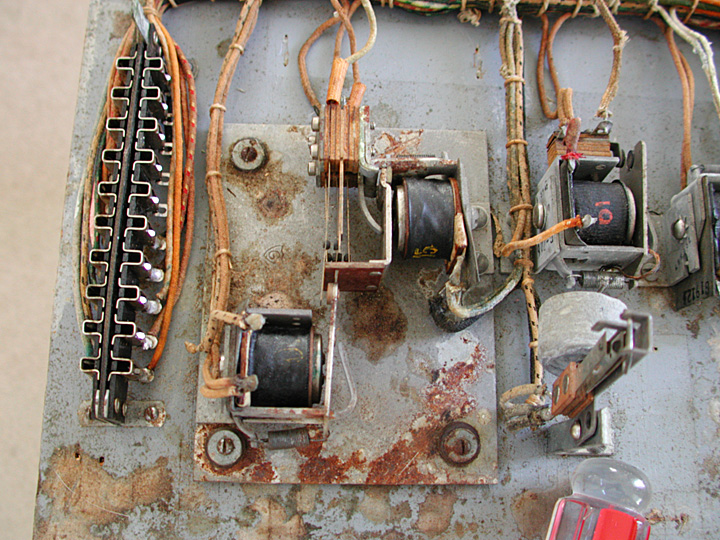
The corrosion was extreme on some of the components. This latch relay was shock mounted but the corrosion and deterioration of the rubber grommets prevented any movement. The original solder used contained a large amount of flux and if not removed, this flux caused excessive corrosion.
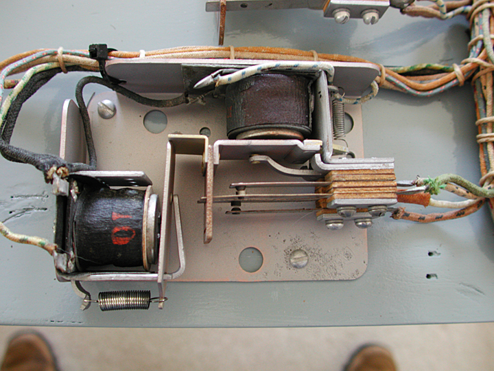
This is a rebuilt latch relay. You can still see how the corrosion has eaten into the plate, near the mounting screw.
This shows some of the hardened grease that was hidden from view by the contact plate.
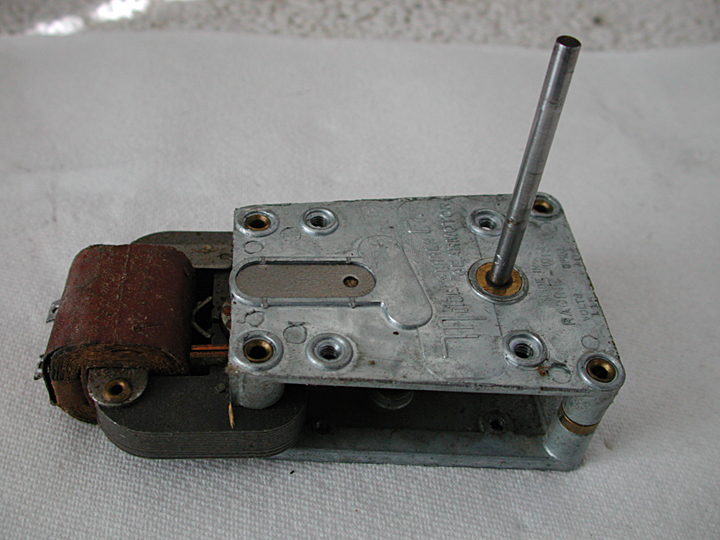
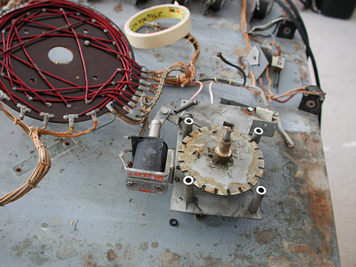
This is one of the score motors. They are not made to be disassembled as can be seen by the rivets that hold the two plates to the standoffs. There is an access plate in the center, with a hole that allows oil to be added. The access plate covers some felt like material that should hold the lubricant against the pinions (axles). The plate hides two of the gears that rotate the fastest.
The plate is not meant to be removable as be seen by the four metal punches that crimp the casting over the plate. The gear train can be cleaned without disassembly but immersing the motor in a ultrasonic cleaner, up to but not including the coil and metal plates. However then the felt will soak up the ultrasonic cleaner and will move around but not remove any previous lubricant. Removing the plate shows some interesting problems.
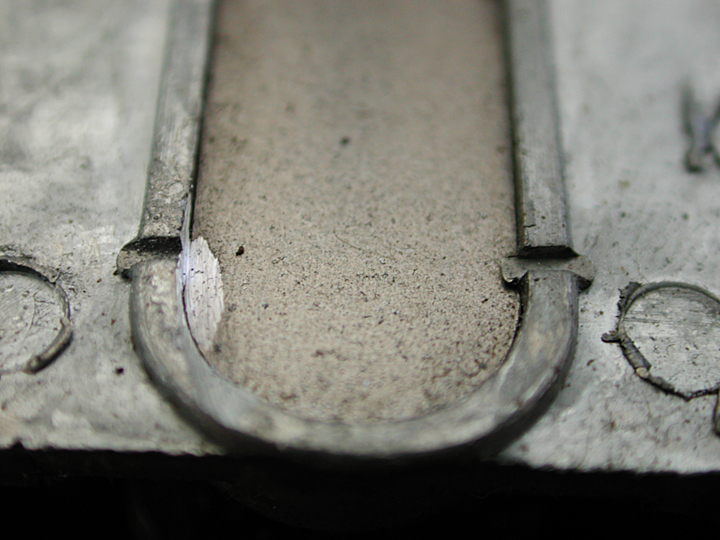
Using a hobby high speed rotary tool (Dremel) and a cutoff wheel, the lip of the crimp can be removed.
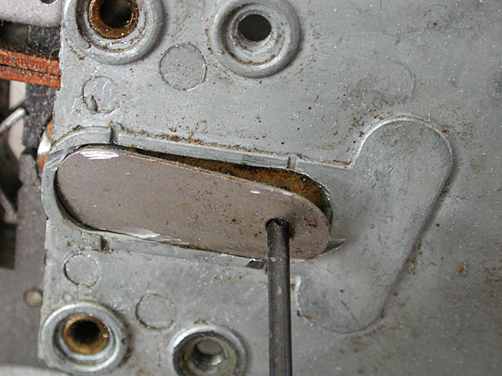
After removing all four crimps, a rod can be used to twist the plate off. The plate can be flattened and then reset in the hole. Normally there is enough binding of the metal to hold the plate in position after reinstallation. The crimps can be renewed to make the location more positive but generally this is not needed.
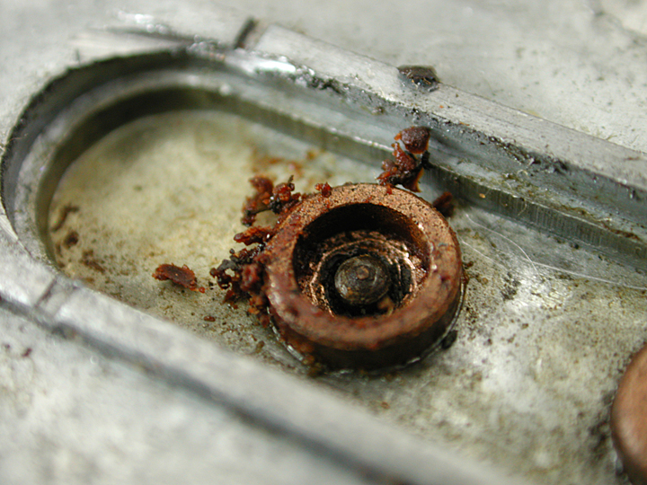
Normally, hardened grease can be found in the cup.
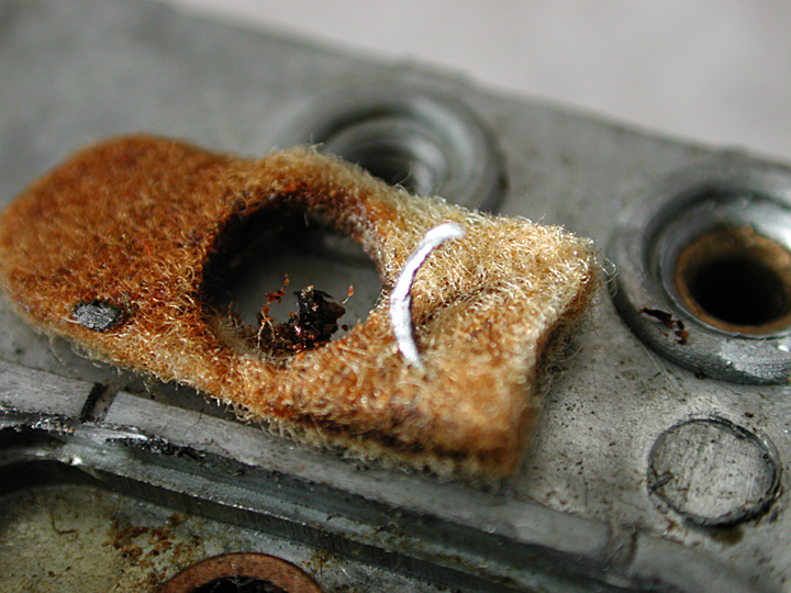
Here is a metal shaving. Some of the smaller pieces are not visible.
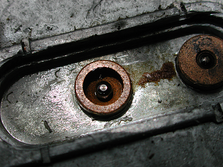
This cup had no grease and was dry.
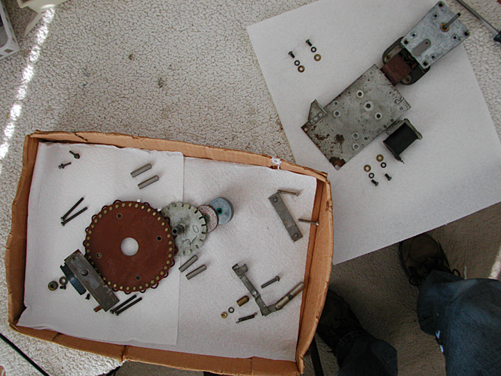
This is a picture of the components of a score motor after it was disassembled. The location of each part is in order and the part generally points to the place where it should be when assembled. For example, the order of the wheels and the leather clutch plate overlap, with the spacers for the contact plate, and their screws, located on top and bottom of the contact plate. The center line of the assembly goes from top right to bottom left, with the solenoid and coin approximately in line.
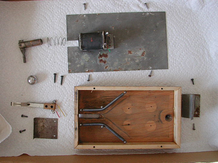
This is the small pinball machine that appears on the relay board. It serves to randomize the play of horses. The mounting brackets were bent so as to reduce the slope and four of the pins removed.
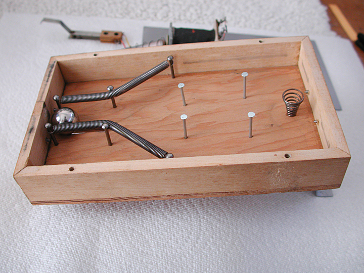
The wood has been cleaned and the pins replaced. The brackets were straightened and the original slope returned. The pinball was relocated to the original spot.
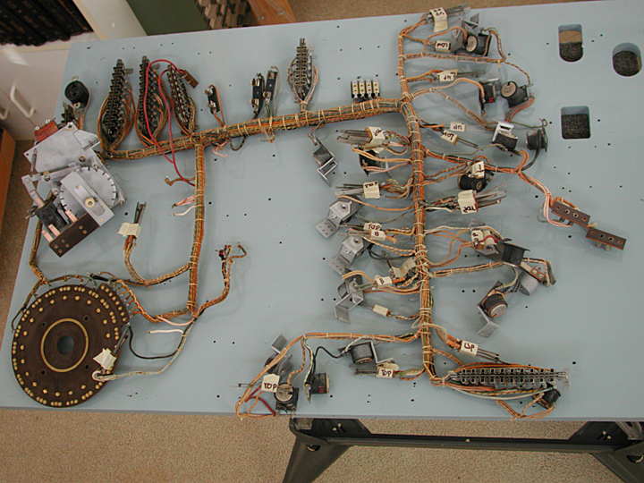
The wiring harness was removed completely and the board repainted. The harness was placed back on the board in preparation for reattaching the components. Each switch stack has masking tape around the stack to hold the leaves in place and the top marked so the stack can be replaced on the relay frame as original.
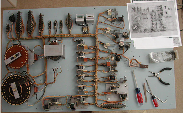
Most of the relays are attached and the score motors rebuilt. Note the photo in the upper right that shows the original locations of each relay.
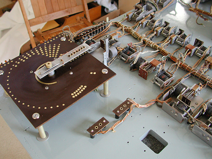
This is the payout score motor installed. The holes on the right and the sockets for plugs are for the payout tubes.
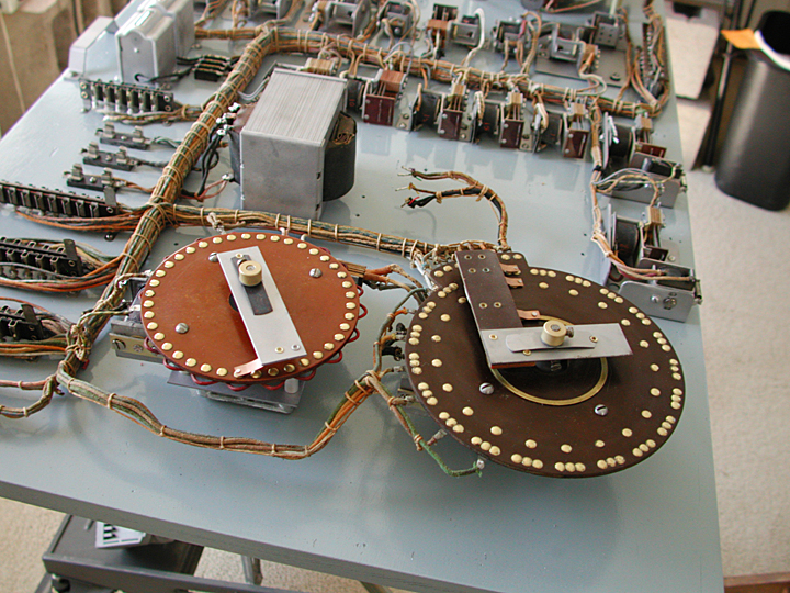
The two score motors are installed. Behind them is room for the pinball which has yet to be installed.
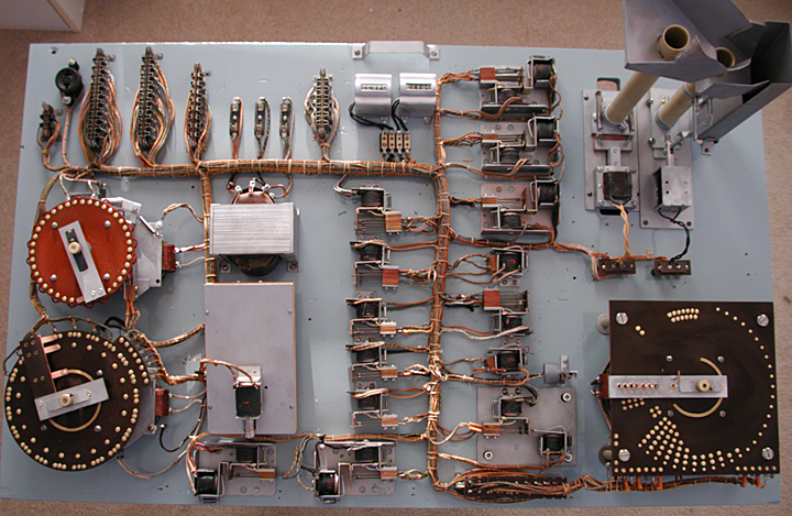
This is the finished relay board. The payout tubes have been rebuilt and added at the top right. The tube on the left is for winning horses and the tube on the right is for the jackpot. The pinball is now installed next to the two score motors on the left. The solenoid kicks the ball into play. The socket just to the left of the play counters, top center, is the plug that converts from free play to payout. Normally this has a plug that is mounted either in the top or bottom of the socket. The labels still need to be reproduced and added.
