Evans Races Final Assembly
(Note: This page was created long after the restoration was finished. There is much missing and some may be incorrect. Sorry.)
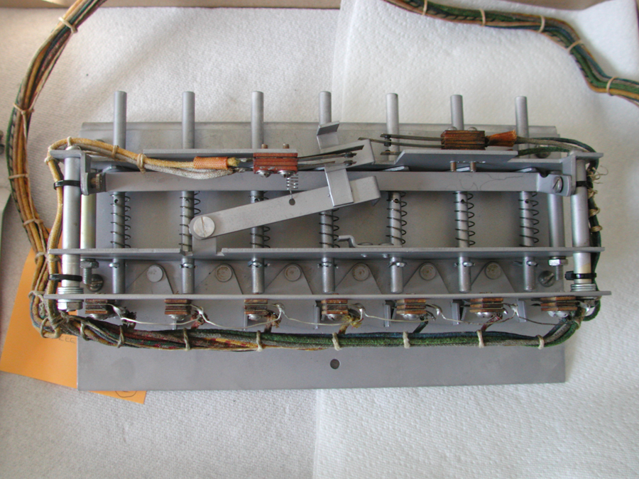
The free play buttons knock off won games. The triangular pieces at the bottom prevent simultaneous pushes.
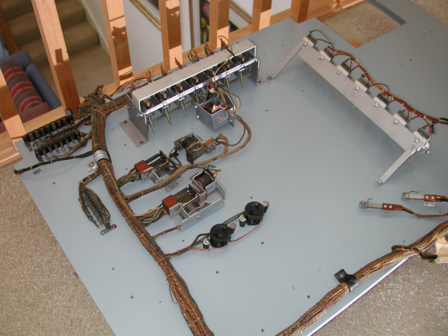
The wiring harness was removed completely and the board repainted. The harness was placed back on the board in preparation for reattaching the components. Each switch stack has masking tape around the stack to hold the leaves in place and the top marked so the stack can be replaced on the relay frame as original.
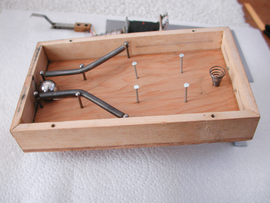
The pinball machine on the relay board provides a randomizing function, providing the horse in the lead when the ball returns to the bottom an advantage.
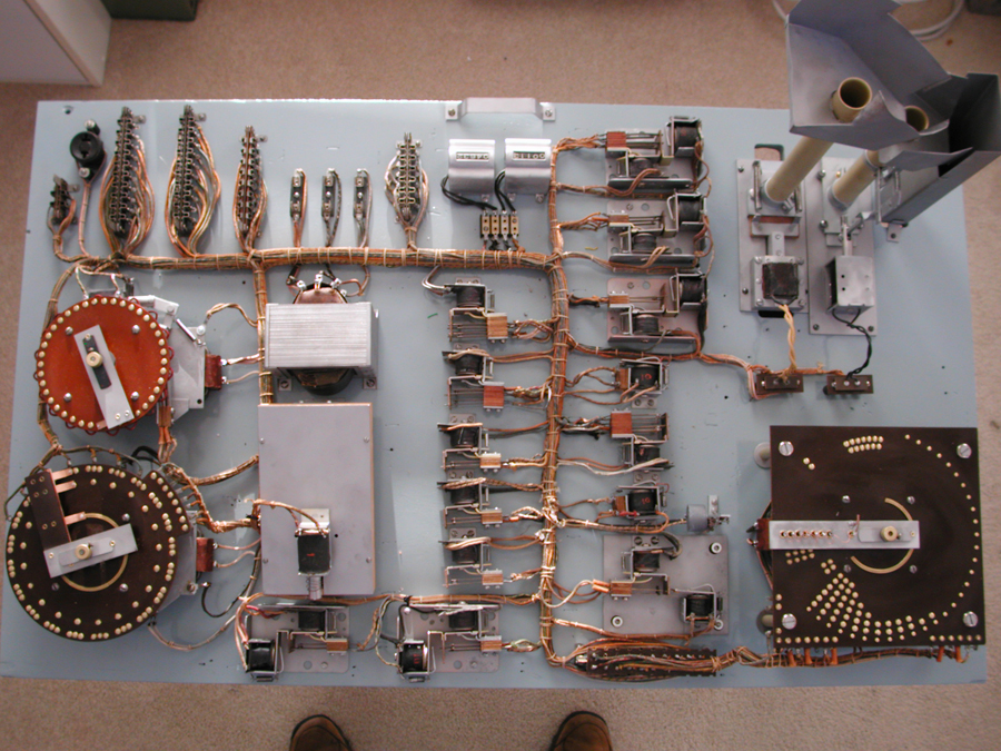
The relay board is finished. The payout tubes are at the upper right with the count stepper driving the slicing off of the nickels. The various start and reset relays are next, in the right center of the board. The pinball is in the bottom left center with the power transformer above it. There are a row of jacks to allow the rest of the game to interface with this board.
The tube on the left is for winning horses and the tube on the right is for the jackpot. There is a plug just below the game counters that converts the game from payout to free play. This plug was removed and a switch with a long wire substituted, allowing the proprietor to switch from payout to free play when the police arrived.
The labels still need to be reproduced and added.
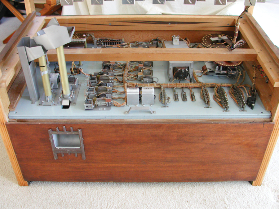
The relay board slides into the cabinet below the mechanism. It can be easily serviced by pulling it out although the plugs must be removed.
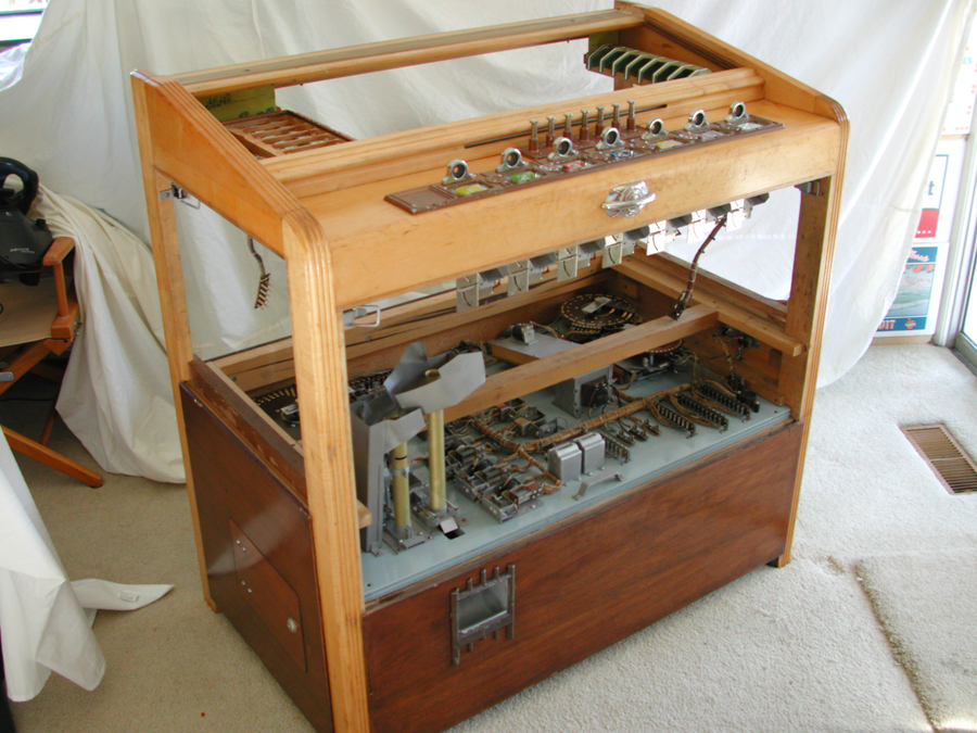
The cabinet has the relay board and the coin mechs installed. The head with the odds wheel and win count is next.
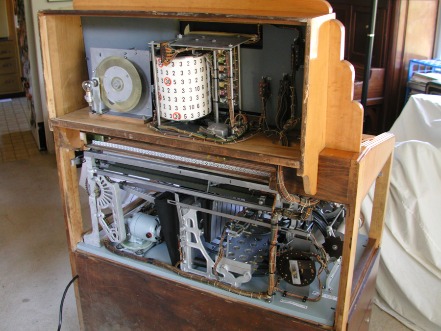
The head unit is installed, including odds drum and win count wheel. The winnings count wheel is used when the game is on free play. The winnings are accumulated on the wheel and the number projected in a small white circle on the back glass. Bets are knocked off one at a time when the free play buttons are pressed. These are not used when the game payouts out coins.
This also shows the mechanism with pneumatics installed above the relay board.

This was my test setup. The mechanical parts are setup outside of the cabinet. The relay board is next to the mechanism board and must be turned around so the plugs can be attached in the middle of the picture. I use a Variac the first time I turn on a game in order to avoid damage due to incorrect wiring. The cabinet is on the right.
