Restoring the Pneumatics
The pneumatics are not mechanical and so require a different approach. Bellows material, valve facing, and pouches are all organic materials. Hide glue, made from cow hide, is interesting stuff. Pneumatics run on air or actually the lack of air, a slight vacuum. So like electricity, you cannot see it but have to use devices to measure the performance.
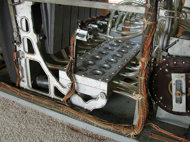
Dirty mechanism, showing the location of the valve box. Note the input tubes, indicating a vacuum at the hole of the piano roll or other event, are on the bottom half of the valve box. The output, signaling the movement of a horse actuating bellows, are coming out of the top half. The pump bellows are at the far left, supplying a vacuum in the manifold box, hidden behind the vertical casting. The tube at the bottom of the box can be seen through the large opening in the casting, supplying a vacuum to the valve box.
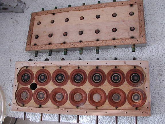
This is the inside of the valve box. The pouches are at the bottom and the valves are sticking through the small holes on the top piece.. Note how the pouches are deformed from repeated actuation and are slightly depressed.
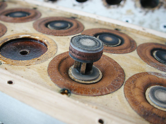
Here is a valve sitting on top of the pouch. The pouch raises when air enters the area under the pouch, see the pouch to the left of the one with the valve. The air entering this area raises the pouch and therefore the valve, letting a strong vacuum collapse the actuating bellows of the horse. The small hole next to the pouch material, partially visible closest to the edge of the box, is the bleed valve. See the explanation on how the valves work.
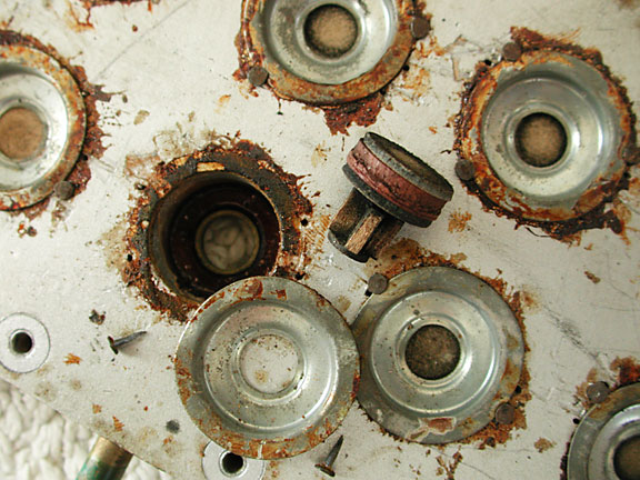
Here is the valve and the top chamber. As the valve raises, it blocks the hole on top which causes the full vacuum to be supplied to the output.
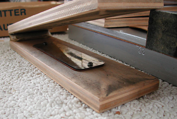
This is one of the pump bellows. Note the flapper valve that allows air to enter the bellows, once it is covered with flexible fabric of course. Note the holes in the top piece of wood, where the air can exit. This removing of air is what creates the vacuum in the accumulator box, which normally is attached below this bellows.
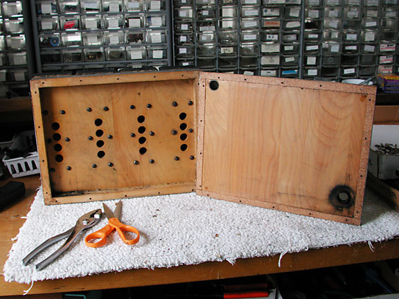
This is the vacuum accumulator box. There are four holes for each pump bellows that evacuate air from this box. The hole in the upper left of the cover plate is connected to the valve box. The bottom right hole normally has a relief valve that limits the vacuum, thus easing stress on all of the pump mechanisms.
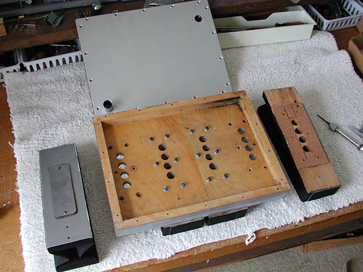
This is the inside of the vacuum manifold which is located on the back side of the four pump bellows. There are two pump bellows mounted, which suck air from the box through the four holes each in the center of the box. The bellows on the right has the cork gasket and is ready to be mounted. The bellows on the left shows the flap valve on the outside, which lets air out as the bellows is compressed and which closes when the bellows expands, extracting air from the vacuum manifold or box.
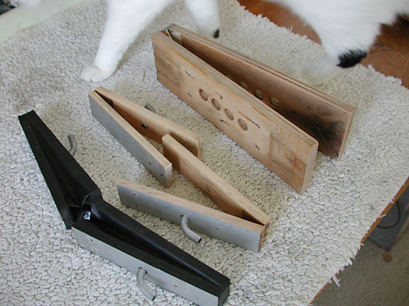
The four small bellows, two covered and two awaiting covering, actuate the horses. The upper bellows with holes is from the pump. The four smaller bellows are used to actuate the horses, moving the horse forward each time the bellows is collapsed. Two of the bellows are covered with rubberized cloth, ready to be installed, and two are awaiting covering.
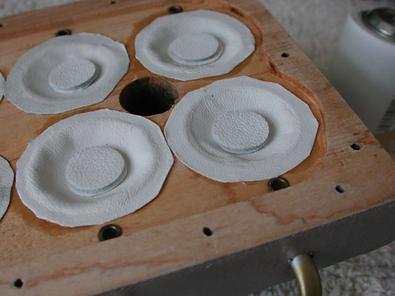
These are the pouches that sense if there is a vacuum. The tiny brass fitting are holes, called a bleed hole, which allow the valve to reset once the piano roll perforation has passed and the vacuum is reestablished.
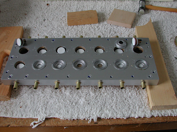
This is the top plate of the valve box. You can see the valves sitting in the holes with some already covered by the retaining flange. The tubes go to the actuation bellows.
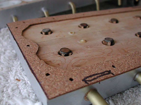
This is the interior side of the valve box, with the valve stems sticking out slightly. The gasket between the two halves is made out of cork and sealed with hide glue on one side.
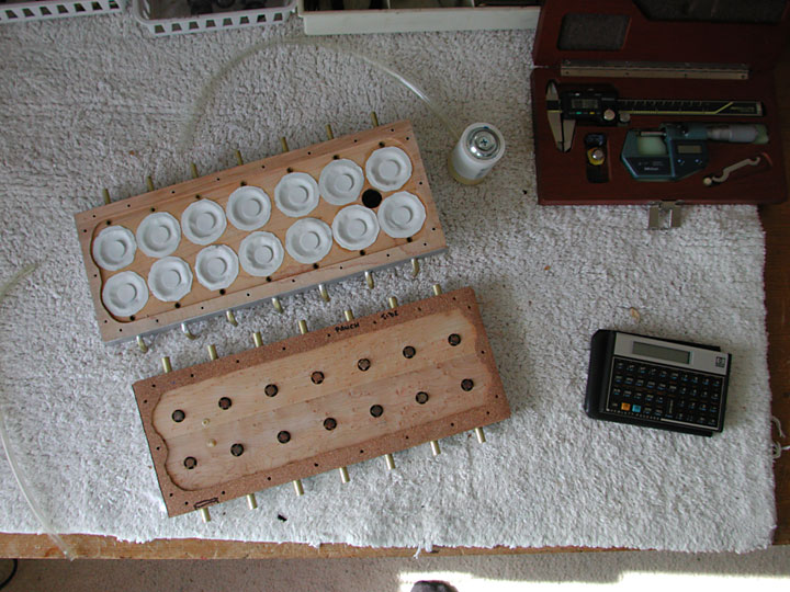
This is the valve box ready for assembly. The valves are on the bottom and the pouches are on the top. The white cylinder with the tube exiting it was used to install the pouches. By sucking air, the pouch is formed into the correct dish shape. Hide glue coats the opening and the pouch is placed into the well. The calculator and caliper were used to determine how much the valve length needed to be shimmed to insure quick valve action.
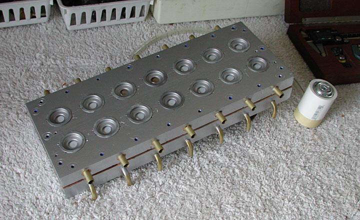
The completed valve box is ready to be installed in the game. The pump extracts air from the valve box in preparation for sensing a hole in the perforated hole in the paper roll. The tracker bar senses the leak which connects to the valve box above through one of the bottom holes. The valve then opens and allows a strong vacuum to extract air through one of the large tubes on top, which then causes the actuating bellows for a horse to collapse.
