Paces Races Restoration March 29
Assemble the crank and left frame. Remove and disassemble pump and valve box.
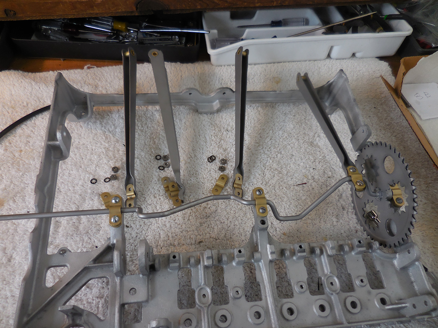
The left frame is clean and now the crank gets installed. Notice how the repair is complete and the added axle extends past the left edge of the frame. The connecting rods are being attached to the crank.
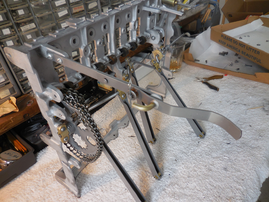
The sprocket has a ladder chain added, the ratchet guides, the wood discs, are added, and some extra linkages, including a damper at the very top, are added.
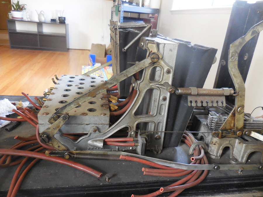
Time to remove another major assembly and restore it. Here is the valve box on the left, the horse actuator bellows in the middle and the vacuum pump on the right.
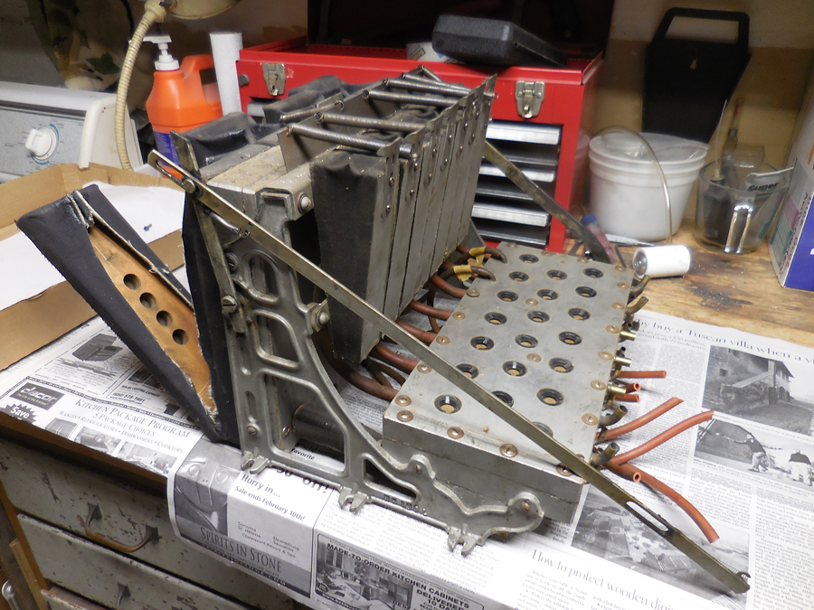
The assembly is out of the cabinet. The left pump cloth is split open and the holes for the flap valve are visible. There are linkage front and rear. The front linkage resets the finish line for the horses as the shuttle goes by. The back linkage helps reset the coins in the coin head.
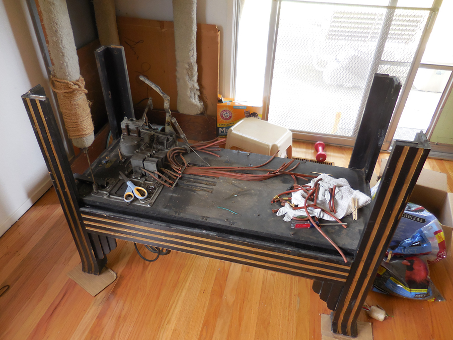
The cabinet is almost bare! One more assembly needs to be removed, the coin payout.
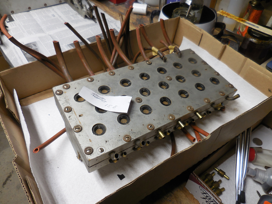
The valve box is the main pneumatic mechanism of the game. It senses a vacuum in a line and causes a strong vacuum to be created in the corresponding line. For example, the valve box senses a loss of vacuum in a hole of the paper roll and sends a strong vacuum to the bellows that makes the corresponding horse to move.
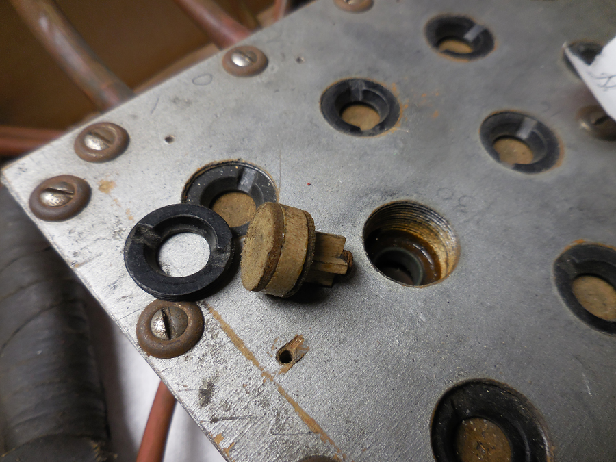
This is one of the valves in the valve box. It consist of a leather button on the bottom, a cross piece of wood, a bottom valve, the support, and the top valve. It is all held in place by the top valve seal that screws into the valve box face. See explanation on how the valves work.
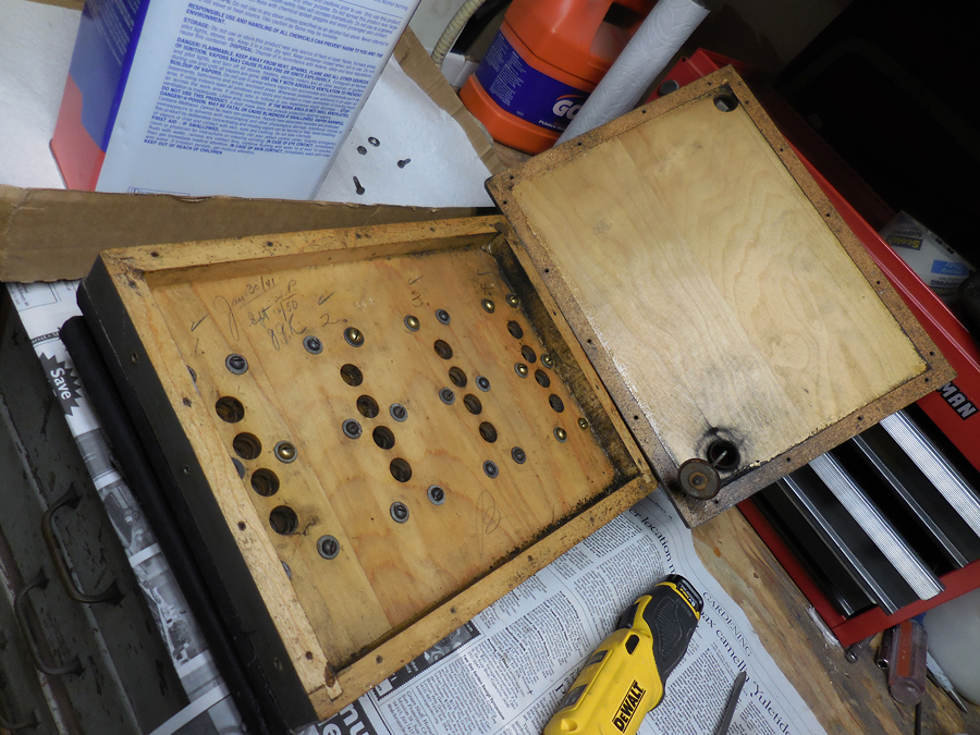
The vacuum box stores the vacuum for use in the rest of the game. The box has the four pump bellows on one side and the horse actuator bellows on the other. The hole in the cover is for a pressure relief valve that prevents too much vacuum from being created. The holes are for each of the pump bellows as they extract air from the box.
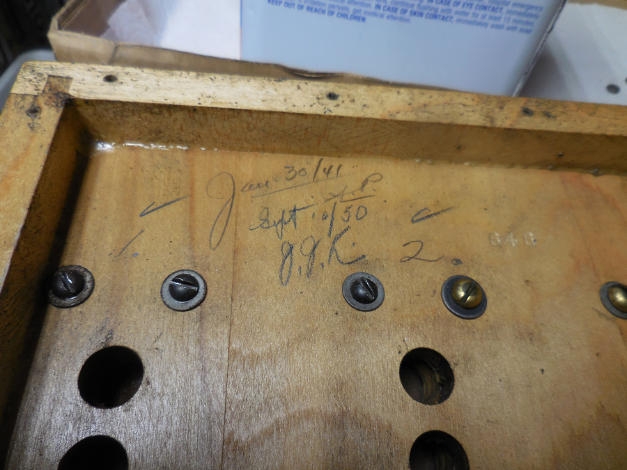
Inside the pump box are some signatures of the operators who fixed the machine. It appears the previous maintenance lasted about nine or ten years before requiring a repair.. The serial number, 648, is also stamped in the wood. Many of the screws holes were stripped and repaired by putting in oversize brass wood screws. The holes were repaired rather than using the over sized screws.
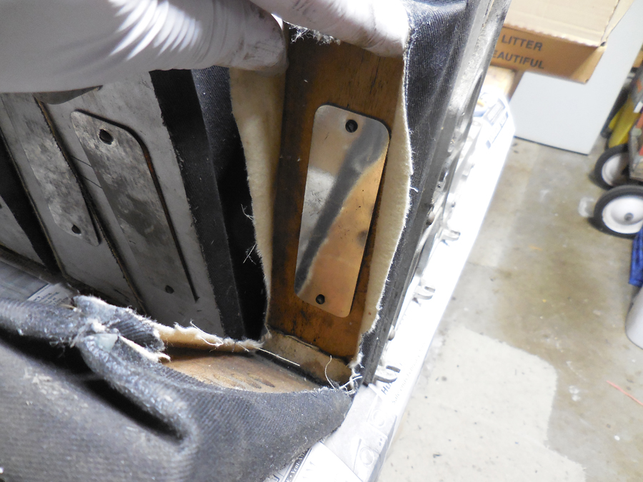
This is the inside of the pump bellows. The flap valve allows the air to go one way and then closes to prevent the air from returning. In this case, the valve allows the air to come towards the viewer, and out of the box, but not return away from the view and back into the box. To the left is the outside of the next valve bellows. The flap valve allows the air to come towards the viewer when the bellows is compressed but the air is not allowed to go back in when the bellows is opened up. See video of air being pumped.
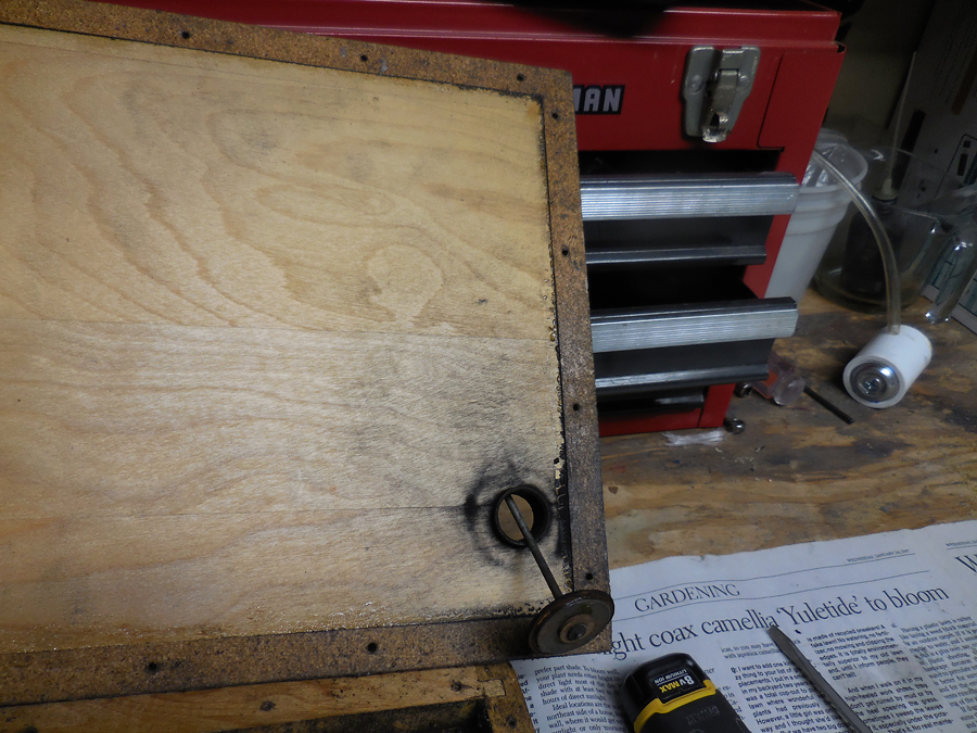
The relief valve is spring loaded. The air tries to get in to fill the vacuum. The spring holds the valve closed until the vacuum is stronger than the pressure of the spring. Measure the spring allows the air in when it reaches about 32 inches of water, much too high. It should be set at 27 inches.
The gasket around the edge of the cover is made out of cork. There are special corks used that are more air tight, with finer grain and more closely packed.
