Coin Payout Parts
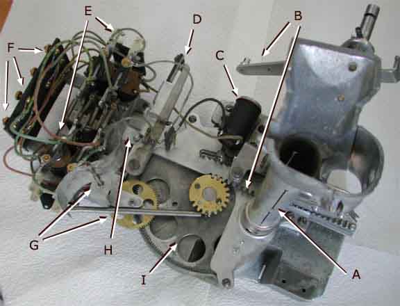
This parts diagram explains the names of the payout mechanism parts as used in the animation of the mechanism.
| A | Coin Feed Tube: The coins are stored here in preparation for payout. It catches coins from the coin slide. | |
| B | Lever and Rack: The player pulls a payout lever which rotates the shaft and actuates a series of levers and springs, which in turn push the rack to the left. | |
| C | Large Electromagnet: When activated, this allows the rack to move and when deactivated, allows the rack to return to the original position. | |
| D | Payout Circuit Breaker: These contacts turn the game on, activated by the smallest movement of the lever, B. | |
| E | Small Electromagnetic and Payout Stop Lever: The small electromagnet is energized by a payout combination on the playfield. It raises the Payout Stop Lever, which will limit the extension of the Rack. The Small Electromagnet also activates the Large Electromagnet C. | |
| F | Terminal: The playfield wiring is connected to the termimal block. | |
| G | Clock: The clock acts as an air govenor, slowing the motion of the payout sequence. | |
| H | End of the Rack: The end of the Rack continues to move until it reaches the Payout Stop Lever. | |
| I | Payout Disc: The Payout Disc as thick as three nickels and rotates to slice off three nickels for each hole. It then rotates back, dropping the nickels in the hole as payout. |
Objectives
The objectives for a coin payout mechanism are:
- store extra coins in a tube in preparation for paying them out
- turn on the game only when the player pulls on the lever, thus saving battery power during normal play
- allow the player to pull the lever any time but only payout coins if there is a winning combination
- payout from three, six, nine, or twelve coins, depending on the winning combination
- make sure the winning combination is fully paid and reset the paid combination so it cannot be paid again
- slow the payout so the mechanism does not get jammed
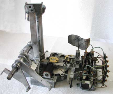
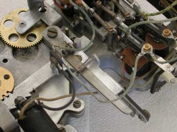
The full payout mechanism shows, from left to right, the levers, feed tube, payout disc and large solenoid, circuit breaker, clock, and small solenoids.
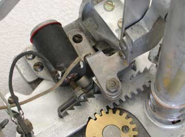
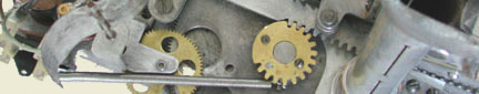
This is the large solenoid. Note the ratchet on the payout rack. In the reset postion, the ratchet prevents the rack from moving to the left. When energized, the ratchet is pulled and the rack can move to the left and causes the payout disc to rotate by the fear at the bottom of the picture. The back ratchet, seen to the right of the ratchet pivot, prevents the player from pulling the rack back until the rack has made it to the payout lever and completed its full extension.
The circuit breaker is the electrical contact in the lower right of the picture. The nut allows a wire connection. Not the peg on the end of the rack. The circuit breaker arm has a set screw adjustment that is activated by the peg, so that the slightest movement of the rack to the right will allow the contacts to close, power the game.
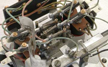
There are four small relays that determine the various payout amounts, two on each side of the rack extension path. Each raises a L shaped lever, limiting the further travel of the rack. There is also a blade contact that will trip the pay combination relay under the playfield, indicating the payout is complete and not to allow it again. At the back of the small solenoid is the contact that powers the large solenoid, indicating the lever has been raised and allowing the player to move the payout rack.