First Shadows
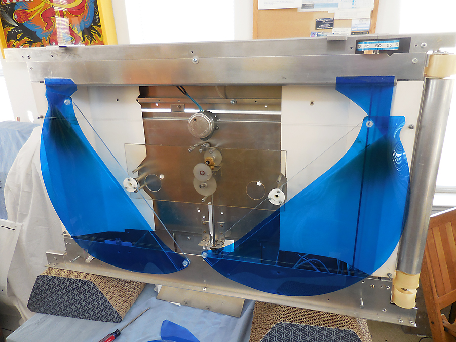
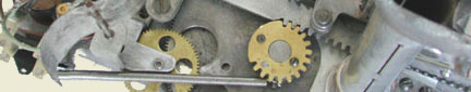
The first blue shadow screens are mounted. They attach to axles which are activated from the back, see below. The shadows go behind the guide strings, top and bottom. There are pieces of white cardboard that provide baffles for the lights. The light is provided by two florescent tubes on either side of the gears and these will be replaced by LED tubes of the same configuration.
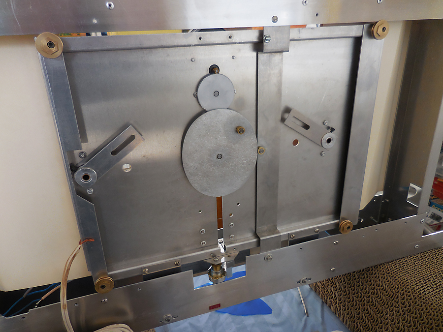
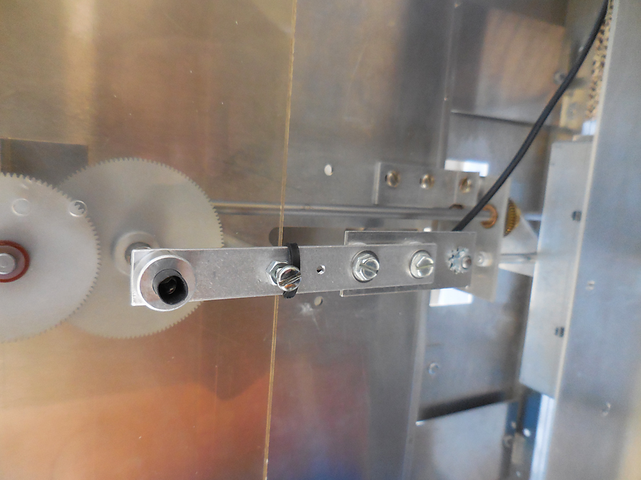
This is the back side of the movable plate. The brass wheels top and bottom guide the plate left and right. The vertical strap has a roller in the middle and the roller follows the elliptical disc. The first arms are attached to the axles, controlling the first blue shadows. Note how short the arms are, especially when compared to the longer arms below.
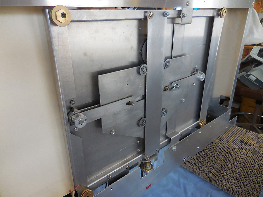
Now the second plate has been added. It has four wheels on either side of the vertical strap, allowing the second plate to move up and down. A second set of arms have been added to control the second set of shadows. The axle is concentric with the first axles. The second set provides a more precise control of the shape of the shadow edges. Note the pivot point of the second arms, much farther away from the axle.
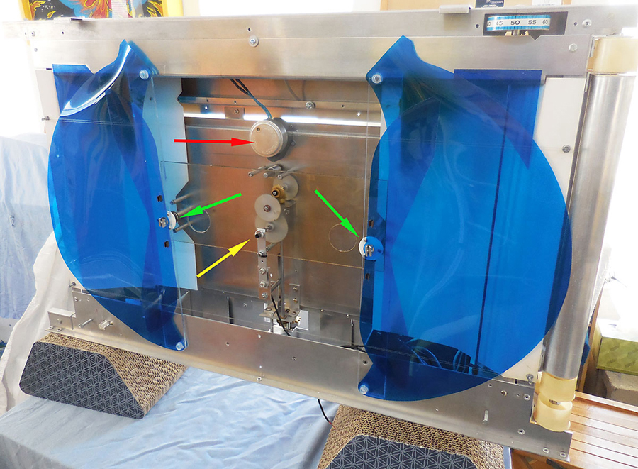
The second blue shadow is now mounted to the inside concentric axle. The yellow arrow shows the analemma and the red arrow the motor that powers the moving plates.
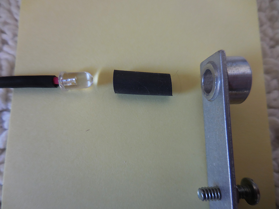
The light emitting diode, LED, is mounted to the arm to position the analemma. A piece of heat shrink tubing allows the light to be mounted in the original hole.
The arm showing the position of the sun is mounted and the LED positioned. The wire providing power needs to be long enough to allow the arm movement.
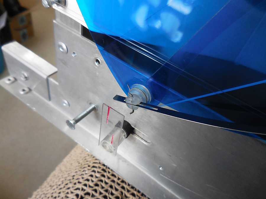
The spring steel bands control the movement of the edge of the shadow. The clear plastic rectangle with the red lines points to the date. There was insufficient clearance between the clear plastic and the springs so I added a black spacer. The design flaw was original to my Geochron and once a year, the band would bind and then scrape the clear plastic, leaving wear marks.
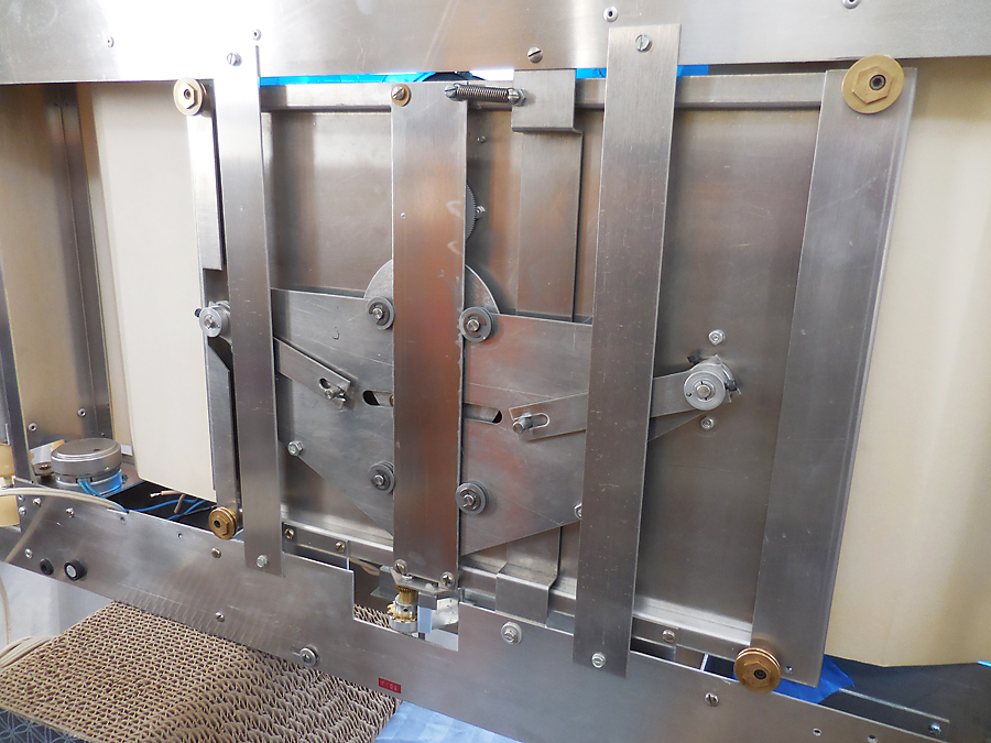
Two more straps were added to stabilize the tracks for the traveling plate. A spring at the top keeps the follower against the elliptical disc. Note the difference in angle between the near arms and the arms on the far side of the plate that moves up and down.
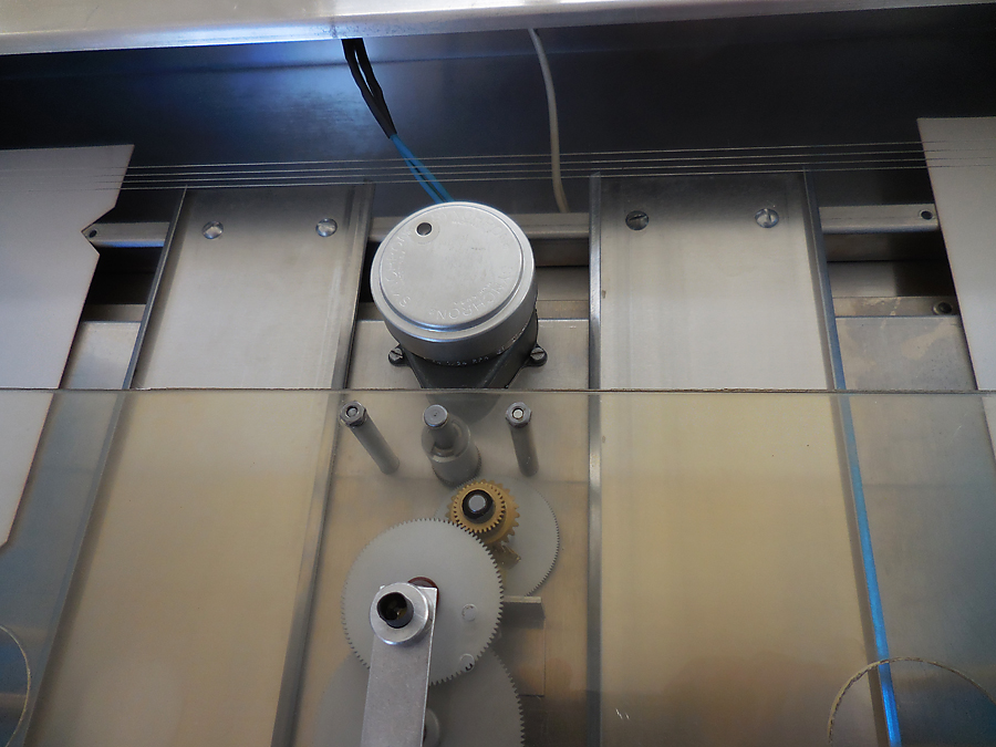
The two light brackets are installed on either side of the motor and gears.
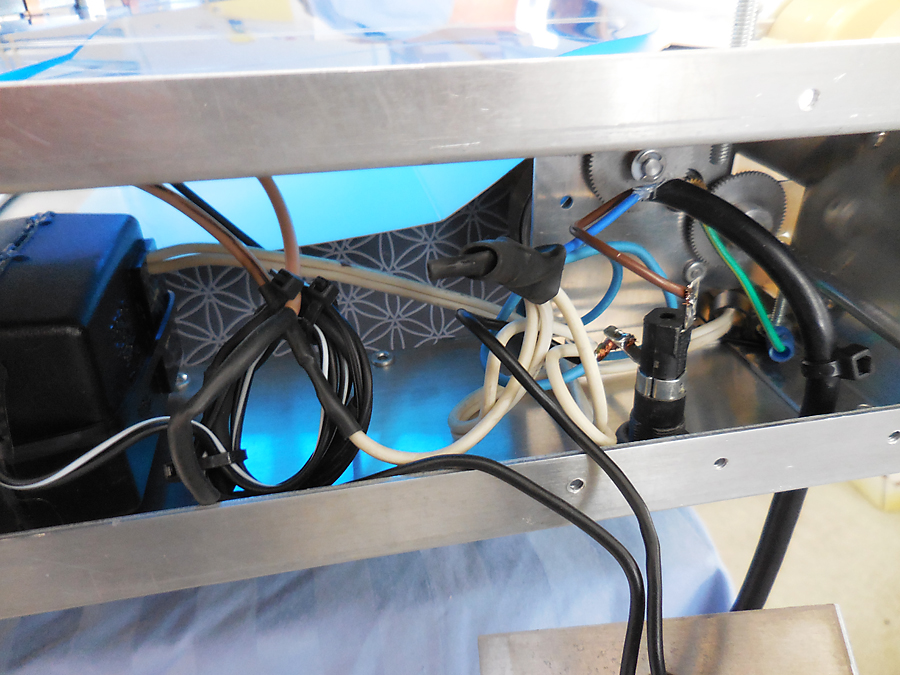
The wiring appears to be a bit of a mess. The power supply for the led is on the left. I am not sure why Geochron did not have a fuse in the original design so I added one. I also used a new three wired line cord and have grounded the third wire to the chassis.
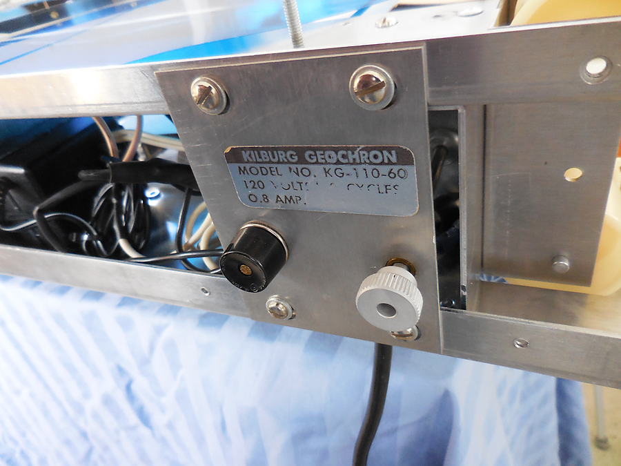
This switch only controls the lights. The axle allows the adjustment of the map, which is actually just setting the time. Kilburg is the original designer of the Geochron and this model is named after him. The serial number is just an embossed piece of plastic similar to that produced by Dymo printers.
Adding the day of the week, date, and map tapes.