Sun and Shadow Table
The Sun and Shadow Table moves on rails inside the Geochron. It causes the sun location to follow the figure eight pattern and the shadow to change depending on the season. I am not sure if table is the right description.
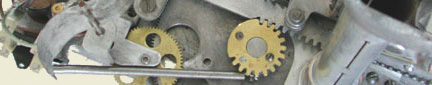
Here are some dirty gears as they were removed. The clear plate that holds the top of the gear pinions has been removed so the gears can be identified and disassembled.
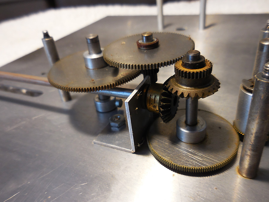
Here are the gears after they have been cleaned.
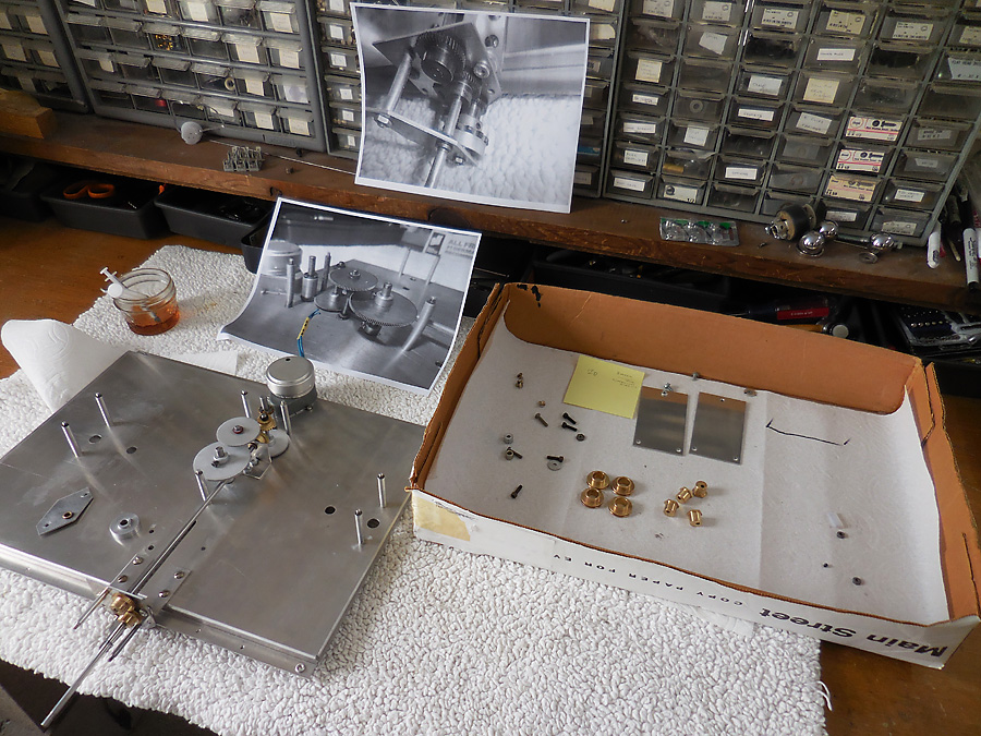
The assembly of the gears is in process with the pictures guiding the gear placement. The oil is at the top left and is synthetic oil. I use a clock repair person's trick to apply a minimum amount of oil by using a needle, dipping it into the oil and passing across the friction surface. The box of parts contains the wheels that suspend the table inside the frame of the chassis.
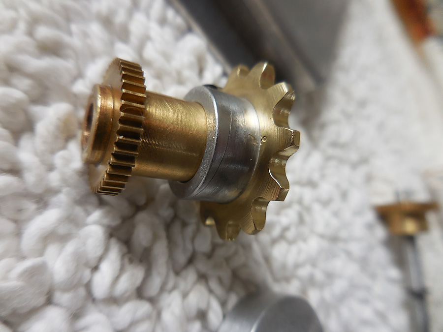
I tend to be compulsive when I clean. I was enjoying it so much after not having restored anything in a long time. This sprocket consists of several parts and so I wanted to disassemble it. The sprocket is press fit on the silver collar. In order to remove it, I heated the assembly and used a fabricated puller. I should have left well enough alone since the exterior of the part was obviously clean. In order to replace the sprocket I had to put the axle in the freezer and heat the sprocket. It went together again thankfully.
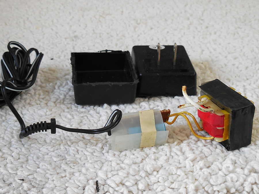
I wanted to convert the Geochron to use light emitting diodes instead of the original florescent lights. There are conversion lamps that use LEDs and are identical in shape as the originals. Some rewiring will be required, see a later page. I also wanted to have the sun position over the earth to shine using an LED as well. The current position is marked by a shadow on the map. A low voltage power supply is needed for the single LED. The power brick or AC adapter is cut open and the transformer and other components removed. The plug teeth, above in the case, will be trimmed away and a line cord connected to the white wires on the transformer.
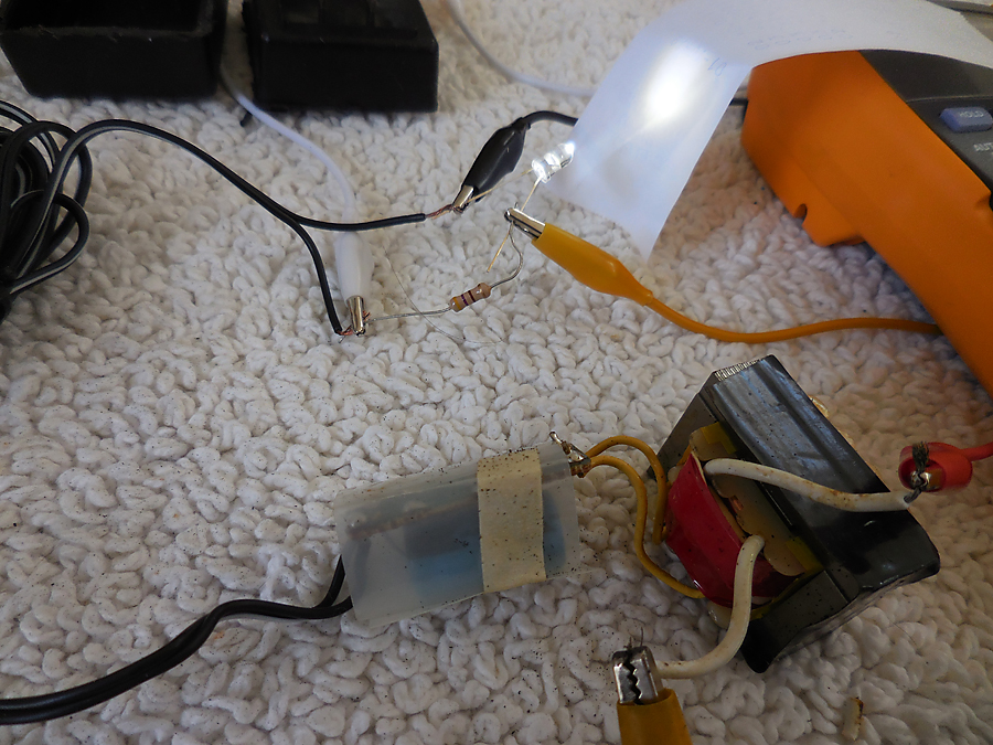
A current limiting resistor is needed to prevent the LED from burning up. Here the line voltage is connected to the transformer in the bottom right of the picture. The white test lead connects the positive output from the power supply to the current limiting resistor, 330 ohms. The yellow test lead connects the current limiting resistor to the long leg of the LED and the black test lead connects the short leg of the LED to the negative lead on the power supply. Now all I have to do is figure out a way to mount the LED.
For those of you who need the data for the led I made a couple of assumptions. Vf was 3.3v, 25mAand I went a bit larger on the current limiting resistor, 470ohms. It is a bit dim on the map so I could either move the mount closer to the surface of the map or go with a 330ohm or even less.
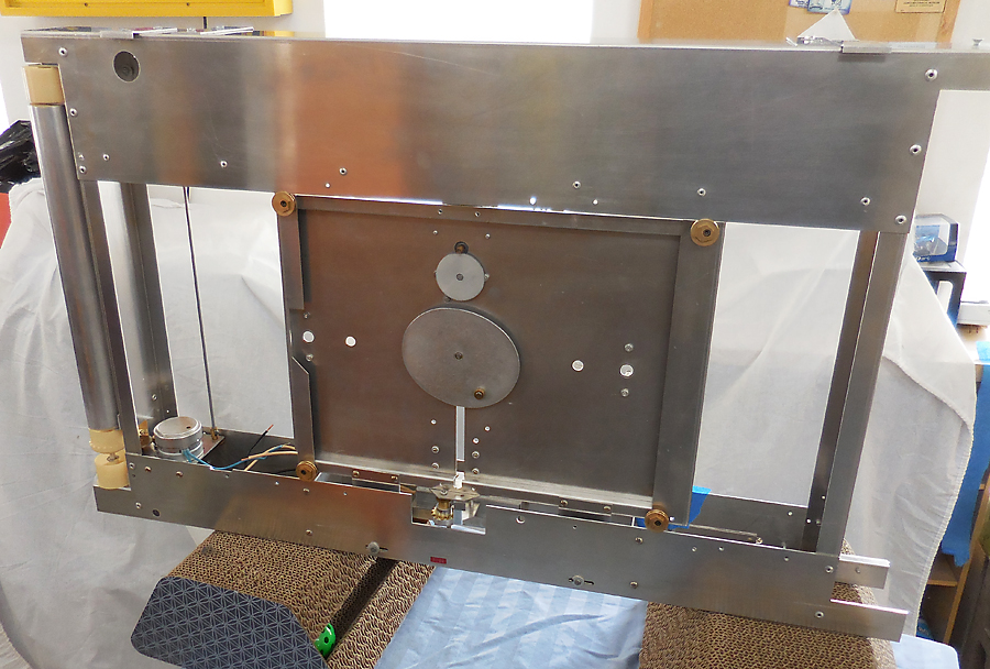
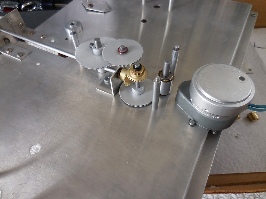
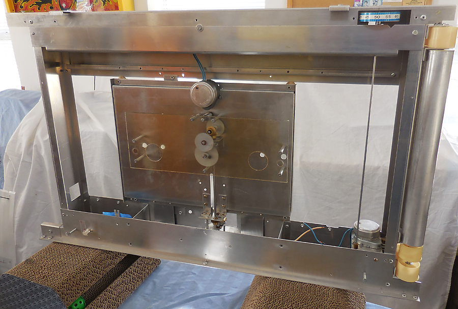
This is the back of the Geochron showing the first part of the movable table. Note the brass wheels that follow the track, both top and bottom. This table moves left and right based by the elliptical wheel in the center.
This is the front of the table. Note how the motor that causes the table to move is mounted on the table itself and moves with it. This motor is a 610 110V 60HZ 3W 2 RPH 9446. It is similar to the map motor mentioned in the previous page except it turns faster. It runs on 110 volt house voltage and is synchronized to the 60 hertz frequency of the alternating current. It is a 3 watt motor and the output shaft rotates twice per hour.
The motor in the lower right drives the roller sprocket which moves the map. It was installed in the previous page.