High Speed Restoration
June 4, 2001
- Part One
- Introduction
- Project History and Philosophy
- Strategy
- Who, Where, and When
- Stages
- Research and Evaluation
- Dismanteling the Old
- Cleaning
- Part Two
- Playfield Restoration
- Playfield Swap
- Top of the Playfield
- Steel Fences
- Plastics
- Ramps, Spinners and Wire Trails
- Part Three
- Bottom of the Playfield
- Wiring and the Cabinet Head
- CPU Swap
- Modifications
- Cabinet
- Assembly
- Game Play
- Summary
Bottom of the Playfield
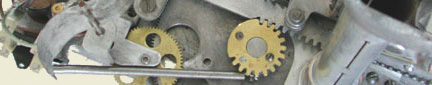
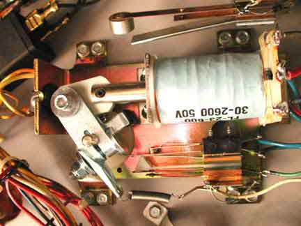
Each mechanical device was restored. I disassembled each mechanism, cleaned all the parts and reassembled it. New coil sleeves were added. New coils were installed if the original coil sleeve could not be removed. An over-heated coil will expand, trapping the coil sleeve in the coil, and consequently will need replacement. Coils also need to be checked to make sure they are the correct. Operators often replaced them on route with whatever is handy.
Finally, all mechanisms were reattached to the bottom of the playfield and resoldered. Diodes and fuses are checked and leaf switches adjusted. It is much easier to make these adjustments on the playfield when it is upside down on the work bench rather than trying to make them after the playfield is installed in the game.
I used some tricks when adjusting the play of the game and how the switches are set. The game is meant for home use and so I prefer it to play fast and actively. Reducing the gap in the switch will cause it to close when nudged by the ball, resulting in faster play.
The sling shot switches are set so the long leaf presses against the rubber ring. This allows it to follow the ring movement in both directions. The short leaf is set with a small gap, a bit less than the standard 1/16 inch.
The pop bumpers have a nylon spoon switch that follows the tip of the skirt. It is important to have the spoon located perfectly so the tip of the skirt probe is in the bottom of the spoon. This way a small tap by the ball will cause the skirt to rise (drop down?) and close the switch. Again, I adjust the switch with a bit less than the standard amount.
I also adjust the flipper so the end-of-stroke switch opens only at the last portion of flipper rotation.
All these adjustments and the close tolerance of the switches, there is some risk of the switch not opening and the coil burning out. Because the game is in the home, most players will notice something is wrong and can turn off the game before any permanent damage. I consider the risk tradeoff of dynamic play versus burned components to be worthwhile.
The flipper assemblies were cleaned and the Nylon bushings replaced. Not only are the cracks in the Nylon difficult to discover but the top wears down from flipper action, allowing the flippers to eventually drag on the playfield surface. The flippers were also modified to the new specification. The modern crank has several modifications, including a new arm for attaching the return spring and a welded tightening bolt that allows one-handed adjustment. A small hole needs to be drilled in the coil bracket to accomodate the new external spring, which now runs from the new arm on the fipper crank to the hole on the coil bracket. The end-of-stroke contacts are filed until smooth and the logic contacts on the one flipper mechanism are cleaned with a coarse business card or paper plate cardboard.
The pop bumpers need to be installed on the top of the playfield in order to allow the lamp sockets inside of them to be soldered to the wiring harness. The pop bumpers suffer a lot of wear and need to be checked carefully for cracks. The metal rings need to be firmly riveted to the actuating rods. The skirts also need replacing if worn or chips are missing. I also add Mylar rings around them, on the play field, to minimize the wear. I also polish the metal rings to a shine in the hopes they will slide on the ball rather than nick it.
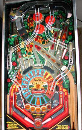
So far, the pop bumpers and slingshots are the only things poking up on the top of the playfield. I have a finished the bottome with the entire wiring, lamp sockets, and wiring clamps and clips. I have boxes of mechanisms, sorted, cleaned, and assembled. I have a new plastic set. It appears like an assembly line at the factory and I am ready to start putting things together. It is time to populate the top of the playfield!
Earlier, I placed an order with Steve Young at the Pinball Resource for all the needed parts, discovered during the disassembly. I ordered new slingshot contacts, Nylon spoons for the pop bumpers, a rubber ring set, new flipper cranks and bushings, and new lamps. Cost for the restoration parts amounts to a bit less than $200, including $60 for plastics, $125 for the playfield (now, $250 or more!), and the rest in parts.
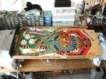
So far, I have spent over 55 hours and all I have to show for it is a new, populated playfield.
Wiring and the Cabinet Head
The cabinet from serial number 88585 had holes on either side of the coin door where the operator had mounted a hasp. The holes were large and the area around them badly scarred. The rest of this cabinet appeared in good condition, with only a couple of small scrapes on the sides. The head box appeared in good condition as well.
The cabinet from the parts game, serial number 93087, was in good condition as well. The cabinet had no scrapes but appeared to have gotten wet at one time and the grain was raised in the wood, causing the paint to flake off around the front left side. The head box appeard in good condition with only a couple of scrapes.
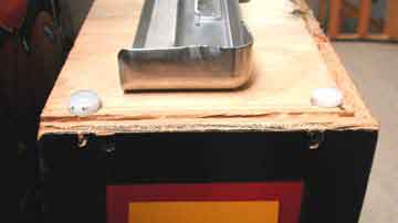
At first glance, my strategy was to use the cabinet from one and the head box from the other. I thought it would be easier to fix the black paint on 93087 rather than fill and paint the hasp holes on the other, and I picked the nicest head. The nicest head had the cleanest electronics and wiring inside the head. I noted the wood on the head was separating near the bottom at the back. Upon closer examination however I was surprised to find the cabinetry in the head in bad condition! The bottom had separated from the rest and had been reattached with the scourge of the pinball repair restoration person, the long, black, Philips head, self-tapping wood screw! The head had four, two on each side, holding the bottom plate to the sides. I had not noticed the small counter sunk holes on the sides because they were in areas where the paint was black anyway. Worse, the person who fixed the broken plate did so without putting it in all the way. The bottom was still sticking out about a 1/16 inch and it would be difficult to remove and put back in the correct position.
My new strategy was to take the cleaner electronics and wiring out of the head and move them to the other head. I had just finished a playfield swap, and now I was going to do a computer head swap! How bad could this be?
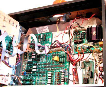
CPU Swap
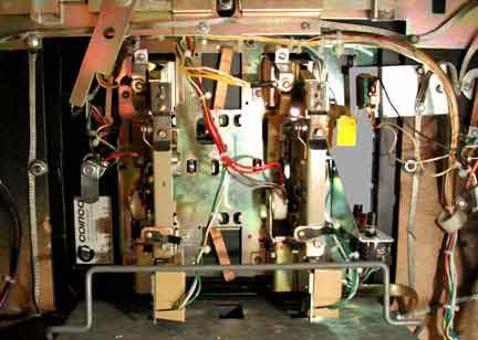
I removed all the printed circuit boards from both heads. I removed the wiring clamps, which screw through the metal sheet and into the back wood. The metal sheet is a radio frequency interference shield and prevents the high speed electronics from affecting your radio, television and computer. If you read the words in the manual and on the back of most of the pinball cabinets, you will find the pinball is classified as a Class B offender in the RFI world, allowing it to be operated in places of business but not in the home. This means it can interfere with many of the electronic devices you have in the home. I do not suppose most pinball players really care!
I removed the metal shield and all associated wiring from the nicer head and moved the shield and all wiring from the old head into the nicer head. It was a lot of effort just to get clean wiring! The wiring clamps were screwed back into the head and the best of the printed circuit boards remounted and the wiring attached.
I delayed mounting the central processing unit (CPU) board as I wanted to make a couple of modifications. See the Clay's excellent site for suggestions and things to check.
Modifications
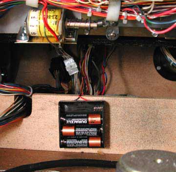
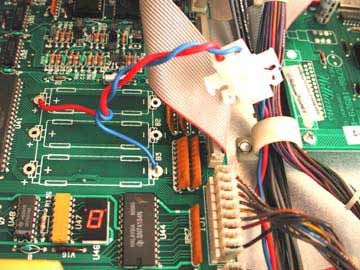
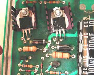
The batteries leak corrosive vapor that attacks the metal traces on the printed circuit board. The batteries can be relocated away from the board or you can replace the batteries with a special capacitor. I decided to locate the batteries in the bottom of the cabinet and so I removed the battery holder from the CPU board. I took a couple of lengths of wire, twisted them together, and soldered one end to the plus and minus holes in the CPU board where the battery holder used to be. I put a Molex connector on the other end of the wires. A battery holder was placed in the bottom of the cabinet, and an equivalent Molex connector added to the wires leading from the battery holder. The connector makes it easy to disconnect the battery and provide maintenance to the CPU board later, if needed.
I was tempted to add connectors to the police light at the top of the cabinet as it was apparent the wiring was an after thought in the design of the game. Wiring went from the bottom cabinet all the way to the top of the light relay and it was difficult to remove the head. I decided to leave it alone for the time being and make the modification if I ever needed to remove the head later.
I added fuses to the diode bridges below the power board, as these are not protected. I also added Molex connectors for the general illumination circuit from the power board. The pin connectors on the edge of the printed circuit board are not capable of passing the high current and the connectors need to be upgraded. Again, I removed the connectors and replaced them with short wire segments leading to a Molex connector. The original connector to the board was removed and replaced with the equivalent connector.
I also replaced the Q1 and Q3 transistors in the high voltage circuit of the power supply. One of the fixes, because the original parts are no longer available, is to twist the legs of the MJE 15030 and 15031 replacement transistors. A more elegant solution, proposed by Jonathan many years ago was to drill another hole, just to the right of the other three prong holes. Now the transistor legs can be inserted into the new hole and the two adjacent original two holes. The legs do not need to be grotesquely twisted but a jumper does need to be added on the backside.
I checked the game and sound ROMs to make sure they were the latest.
Cabinet
The lower cabinet contained the normal dirt and particles found in a game 15 years old. I put it on end and vaccumed it out. Then I washed it with liquid detergent and quickly dried it. I did not worry about raising the grain further and preferred to get it as clean as possible. Cigerette smoke, grease, hand prints from the ages all need to be removed, especially if any paint touch up work is to be done. I have touched up paint in the past, on a cabinet that was not cleaned first. Upon cleaning later, I found the touch up paint to be dull and a bit darker, as it matched not only the paint color but also the dirt covering it. After touching up a couple of places and letting the paint completely dry, I applied a couple of coats of wax.
I replaced the flipper switches because the contacts were severly worn. They carry high current because they still directly drive the flipper coils. Consequently, they arc and cause metal to jump from one contact to the other.
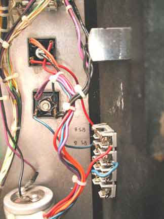
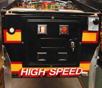
I removed the coin door and did a separate restoration on it. All components and wiring were removed and the door components carefully cleaned. The door had been kicked sometime in the past and I carefully pressed it back out. The door is actually double thick metal and I used wood wedges made from old fashion clothes pins to push out the outside layer and keep it out with reinforcement from the inside layer.
I also removed one lead from each of the coin lock out solenoids. These solenoids tend to buzz. They hold a reject pin out of the way, and allow the player to drop a coin into the machine. Once the game has a maximum number of credits accepted, the solenoid drops the pin into place. Further coins will just drop through to the reject trough. Since I am going to place the game on free play, the solenoids are not needed and the game is quieter as a result, at least as quiet as a pinball can be!
The door was repainted black and reinstalled. I polished the legs with Semichrome and waxed them as well. The wax keeps further tarnish from forming.
The game is ready to be reassembled and played!
Assembly
I put the legs back on the cabinet and put the head unit on. I placed the new playfield assembly inside the cabinet and connected all the wires. All plugs seemed to be connected in their correct positions, and the numbering I placed on the plugs at disassembly helped tremendously.
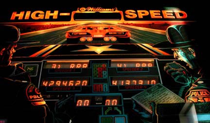
I selected the best four displays from the two games and the display driver board and placed them in the head box. I ran into my first problem! The backglass would not slide down into the slot correctly and was coming close to being scratched on the lamp shields around the ball-in-play lamp.
The speaker grill holes were not aligned for the speaker grill from the other head unit. With the game now almost assembled I needed to reposition the L bracket holes, so the backglass could slide down and fit into the groove and still clear the lamps and shields.
The game was ready to be played. I turned it on and it loaded the three balls into the ball feed. I waited and it appeared ready, indicating factory setting were installed. I dropped a coin and started to play. It always amazes me when a game works the first time it is plugged in. I thought of all the connections, all the wiring I had done, and all the opportunities there were for me to make mistakes. I also remembered all the quality checking time I spent, looking for my mistakes and all the mistakes I found then. I considered my time well spent then and now.
Remember the red, yellow, and green lamps that were backward. I discovered them now and switched them. I guess I did make a couple of mistakes afterall. I also was not happy with the aim on a couple of the ball fences and fixed them as well. The pop bumpers were not sensitive enough, nor were the slingshots. I decreased the gap on their switches and happily turned the game over to the kids for some game burn in time. After they did their worst to break the game, I got a chance to play.
Game Play
I think this is the reason I started owning and restoring my own pinballs. You can set them up the way you like, making them play perfectly. The game was fast because the playfield was slippery. All the impulse machines, the pop bumpers, sling shots and flippers, were quick to act and powerful.
The ball made the loop and headed straight back to the flipper. If my reactions were better, I could make loops all day.
I noticed an amazing effect of the slippery playfield. The ball might have a lot of spin placed on it from some travel along a rubber ring. Imagine if it was traveling slowly in a particular direction and then was to encounter a rubber piece. Suddenly the ball will spring off in another direction! The ball has a tremendous of horizontal spin imparted to it and that spin is maintained because of the slippery playfield surface. However, when the ball touches a rubber piece, that spin suddenly sends the ball off in a new direction, with lots of speed. Suddenly the player now needs to watch for ball spin as well, and since the balls were newly polished, this is difficult to detect.
Summary
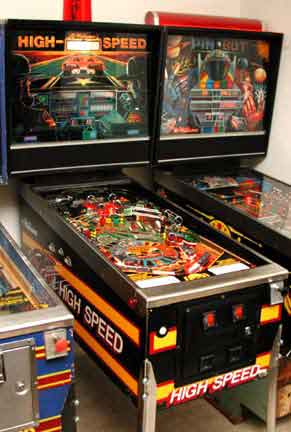
I now have an almost new High Speed Pinball in my collection. The lights flash, the game makes sounds, and the ball ricochets around, much to the delight of the player.
It took a lot of work but watching people play makes it all worthwhile.
Information Sources and References
- rec.games.pinball
This is a news group on the Internet. Many professional operators, competent hobbyists, and parts suppliers hang out here and many offer good advice and services.
- PinballHQ.com (http://www.pinballhq.com)
CFH (Carter F. Hardwick III) provides one of the best web sites for pinball maintenance. There is a wealth of information, great pictures, and some good old advice.
- Tim's Audios and Videos
Tim Arnold has made a series of videos that show his collection and intersperses interesting technical tidbits amongst the videos of his games. He also released audiotapes called If It Ain't Broke, Don't Fix It.
- The Pinball Pasture (http://www.lysator.liu.se/pinball/)
David Byers's wonderful site has supported the hobby for years. It contains a pinball database, instructions on how to play, a glossary, a serial number database, and links to other pinball related sites.
- The Pinall Resource
Steve Young provided all the parts. Of course, he made me pay for them all. Support your pinball parts supplier. Steve does a great job.
Thanks
My thanks to Jonathan Deitch, Bill Ung, Robert Johnson, Don Wright, cfh, Cliffy, Lynne, Elisa, Dustin, and Ryan, for advice, help and support.
Author
Michael Sands is the proprietor of The Sands Mechanical Museum, a virtual museum found at http://www.sandsmuseum.com. Tours are available by appointment. He has been restoring games for over 15 years and has recently retired from the high technology world to devote more time to his hobby (business?). He offers museum quality restorations and is happy to talk about old coin operated machines.