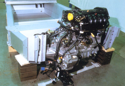
Rover K-Series from the MG-F mounted in the chassis.
Adriaan Briene wrote an exceptional article about the Rover engine and the original pdf is included as well.
The VVC principle is based on an eccentric rotating disc to drive the inlet valves of every two cylinders. Since eccentric shape creates non-linear rotation, the opening period of the valves can be varied by controlling the eccentric position of the disc.
The basic concept was developed by a mr. Mitchell and it was published and patented back in 1973. However no one used it and it was forgotten until Rover re-discovered it. In 1989 Rover began experimenting with the system and in 1993 had developed a 1.4 litre version with VVC.
With VVC the outlet camshaft isn't part of the VVC system and is driven normally by the toothed belt from the crankshaft. If Rover would have driven the entire camshaft from one eccentric disc then only one cylinder would benefit from the speed variation. For one cylinder the camshaft would run at low speed when opening the inlet valves giving long duration and when the valves would be closed the camshaft would run at a higher speed. Now the inlet valves on the same camshaft for another cylinder would run fast when the inlet valves were opening and would run slow when the valves were closed. Totally unacceptable! So every cylinder needs to be driven from the eccentric disc seperately!
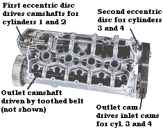
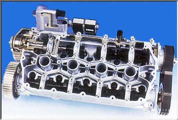
For the K-series Rover opted for two eccentric disc's whereby each disc is driving the inlet valves for two cylinders. The picture of the VVC head explains things.
- The lower cam is the outlet cam driven from a toothed belt (belt not mounted in the picture).
- The first eccentric disc at the top left is also directly driven from the toothed belt
- The second eccentric disc at the top right is driven from the outlet cam by a separate toothed belt (the belt at the right side of the head)
- The first eccentric disc (topleft) drives the inlet camshafts for cylinders one and two
- The second eccentric disc (top right) drives the inlet camshafts for cylinders three and four
In principle every cylinder has it's own cam.
- The camshaft for cylinder one is driven by eccentric disc no. 1, it is hollow to allow passage for the cam of cylinder two.
- The camshaft for cylinder two is driven by eccentric disc no. 1 it is running partly through the hollow camshaft of cylinder one.
- The camshaft for cylinder three is driven by eccentric disc no. 2 it is running partly through the hollow camshaft of cylinder four.
- The camshaft for cylinder four is driven by eccentric disc no. 2, it is hollow to allow passage for the cam of cylinder three. (Original read two, thanks to LWF Leicher for correction.)
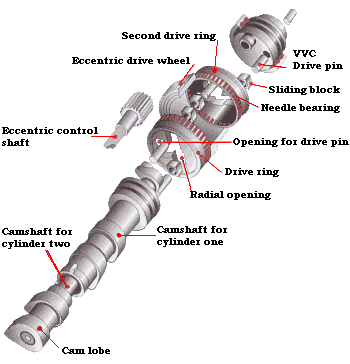
The picture above, nice one isn't it?, explains the eccentric drive. At the top we see the main drive. It is driven by the drive belt from the crankshaft and so turns with constant velocity. The main drive has two driving pins, one for every camshaft. Also notice the angle of 90 degr. between the locations of these driving pins! This to make sure that maximum speed is achieved when the valves are not lifted.
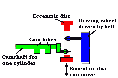
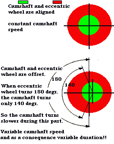
The driving pins drive the two drive rings. The axis of these drive rings can be moved so that the axis from the main drive and the rings don't align. This means the rings don't rotate with constant velocity. The bigger the distance between the axis of the main drive and the ring the bigger the velocity changes. A sliding block compensates for the misalignment of the main drive and the rings.
Each one of the two rings drives a camshaft. The camshafts are driven through a driving pin which can slide in the ring by means of a sliding block to compensate for the misalignment of the camshaft axis and the ring.
The outer area of the eccentric wheel doesn't rotate with the camshafts (The inner part does!) but is rotated by a control shaft. When it is turned it pushes the axis of the eccentric rings away from the axis of the main drive.
The control shaft is operated by a hydraulic cylinder and a rack and pinion drive. And finally this hydraulic cylinder is operated by two elektromagnets who are driven by the engine's management system.
Now this all sounds pretty complicated, and actually the Rover setup is one of the more complex Variable Valve systems around, but therefore also one of the best! With the VVC system the duration of the inlet camshaft can be varied between 220 and 295 degrees. Valve overlap changes between 21 and 58 degrees. This makes the engine very flexible to drive!
The VVC engine can be found in the Rover 200 Vi, 200 BRM, MG-F and in the Lotus Elise 111S. But it wouldn't surprise me if we see it in more applications.
There are a lot of manufacturers who have variable valve control systems. There are three basic variants:
- Cam phasing, The timing of the cam is being altered, the duration remains the same
- Cam lobe switching, A hydraulic system operates the valve from one of two lobes
- Variable duration
At this moment (Jan 2001) Rover is the only one who has a mass production engine with a variable duration of the camshaft. A bigger duration has more effect on power than opening and closing the valve later as with cam phasing systems. The Rover system is without a doubt far superior to all the cam phasing systems. It would be possible to incorporate a cam lobe switching mechanism to switch to a higher lift cam lobe as with Honda's VTEC. This would give the Rover engine the best of all worlds.
And to make it a mechanical marvel.......
please Rover, make it a V8.......
4.0 litre 32V quad-OHC VVC.......Yummie!,
300 bhp would just do nicely, thank you.
Rover K-series Engine, General Information
Rover makes the ideal engine for the Lotus Elise. It is light and compact.
It was originally conceived as a 1.4 liter in an all-alloy, belt-driven twin-cam 16-valve K16 version and was later enlarged by a longer stroke to 1,796cc for the MGF. The engine design was published in 1973 and then originally showed in 1984 and later appeared in the Rover 200 in 1989, and in the MGF launched in 1995.
The weight was 287 lbs (130 kg) with transmission and originally produced 118 hp, an excellent power to weight ratio. It used hydraulic, self adjusting tappets and Bosch multipoint fuel injection.
The engine was constructed in layers of alluminium alloy held together by ten 16 inch through-bolts, from head, through the cylinder assembly and into the crank webbing. This added strength by keeping the structure in constant compression. In stead of fixing the crankshaft in place with separate main bearing caps bolted to the underside of the block, the K-series borrows from racing engine practice. Thus, it uses a deep sided bottom casting, another ladder like the cam-bearing one above, and closed by the sump, which is a conventional steel pressing. When bolted in place, the combination of the main bearing ladder and the block gives the K-series engine an immensely stiff bottom end. This means the engine can safely exploit high crankshaft speeds, vibration is reduced, there is better support for the main bearings, and because the engine is deeper and stiffer in all places, it can be made lighter.
In 1997, Lotus displayed the Very High Performance Derivative (VHPD) version of the K series engine. This engine featured a modified cylinder head with solid valve lifters which allowed an 8000 rpm limit, carbon fiber air box, oil cooler, and lightweight exhaust. This version produced 190 hp.
In 1999, Lotus introduced the 111s version of the Elise. It provided 143 bhp at 7.000 rpm and 128 ft-lb (174 Nm) with the new variable valve control (VVC) version of the K engine. There were larger inlet and exhaust valves, a new aluminium inlet manifold, and a revised plenum chamber. The sequential fuel injection had adaptive control and distributorless ignition used individual coils for each cylinder.
Finally, in June of 2002, Lotus introduced the S2 Elise. The engine continued to use the variable valve control system but now has higher compression, larger intake and throttle body, and modified exhaust. The engine now used the Lotus K4 engine management system, allowing it to produce 156 bhp at 7,000 rpm. The torque now peaked 550 rpm earlier but was still the same 129 ft-lb (175Nm).
